
Water pump for vehicle

A water pump, vehicle technology, applied in engine cooling, climate sustainability, road transportation, etc., can solve problems such as increase in size

Inactive Publication Date: 2015-02-25
AISIN SEIKI KK
View PDF6 Cites 0 Cited by
  • Summary
  • Abstract
  • Description
  • Claims
  • Application Information

AI Technical Summary

Problems solved by technology

Therefore, the friction clutch disclosed in JP2001-200860A would include an inefficient magnetic circuit, and therefore, in order to attract the armature part, the electromagnetic coil and the friction clutch would need to be increased in size

Method used


Image

  • Water pump for vehicle
  • Water pump for vehicle
  • Water pump for vehicle

Examples


Embodiment Construction

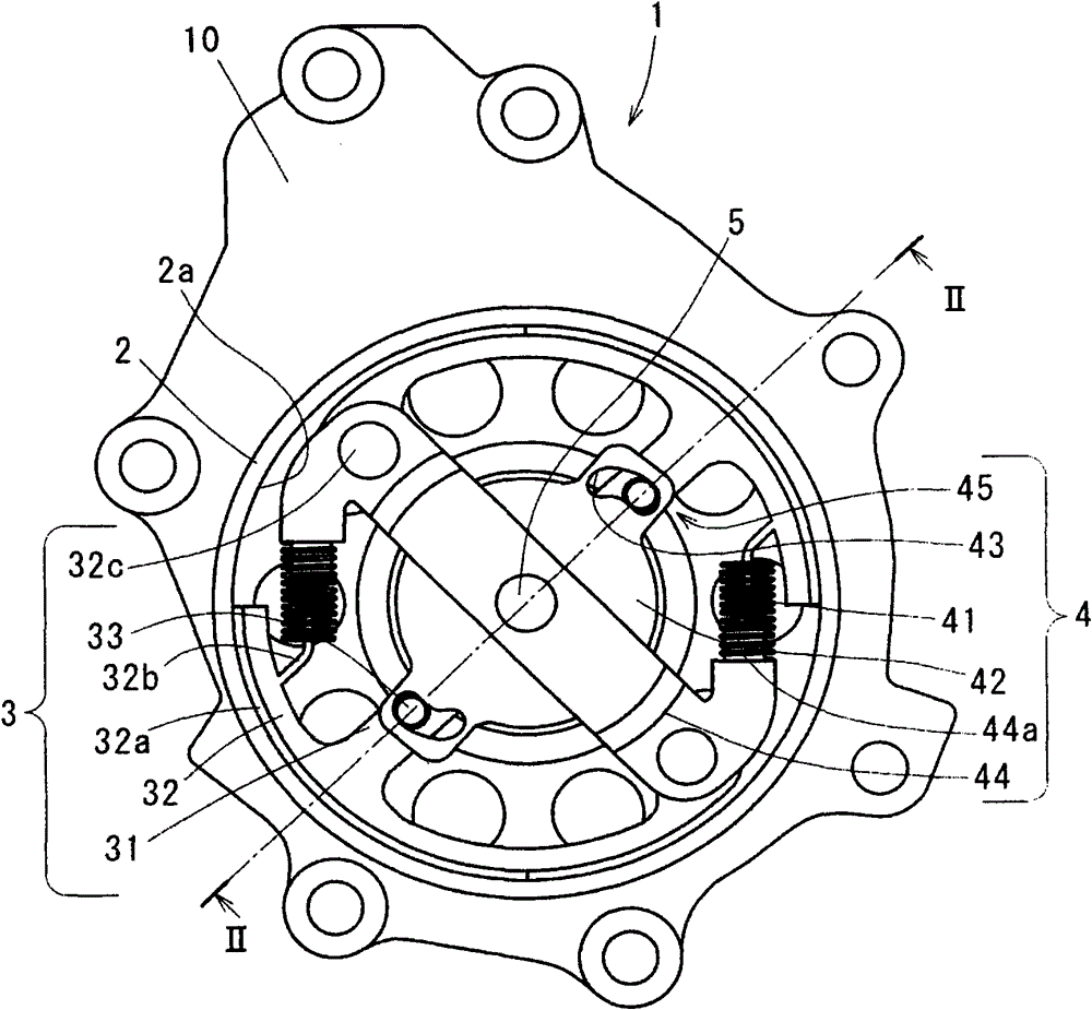
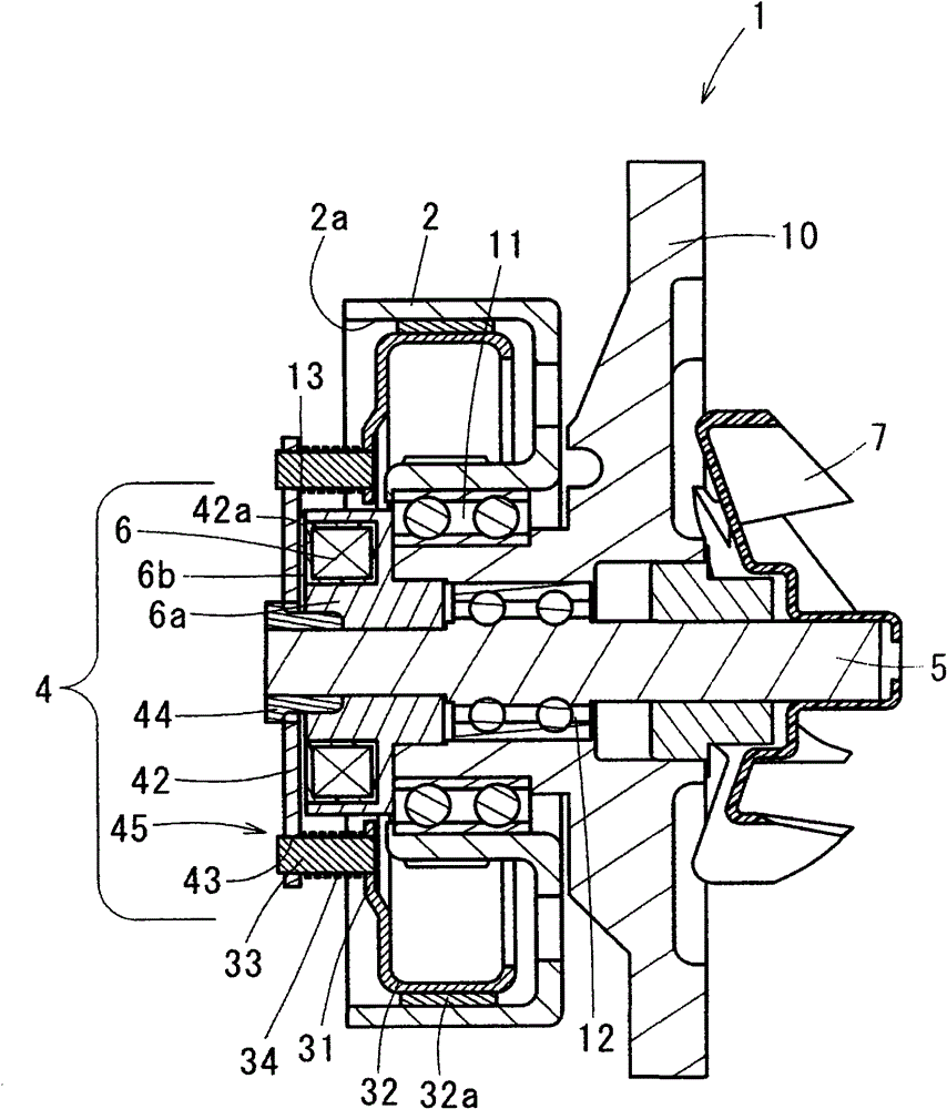
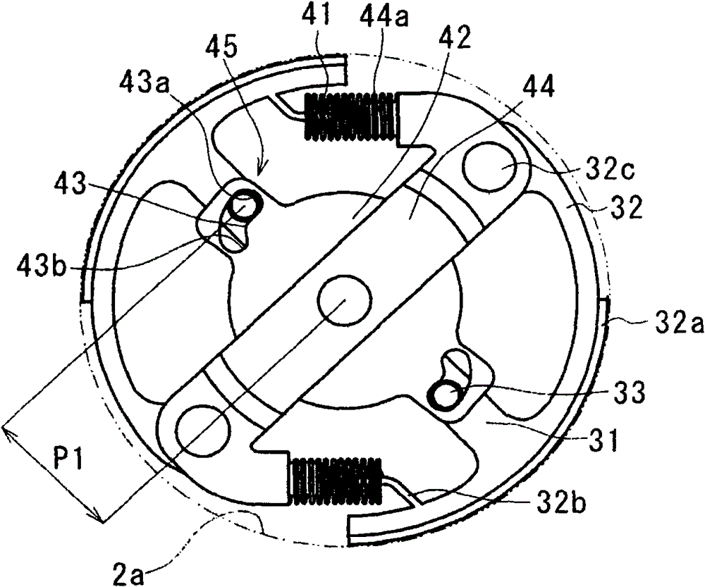
[0034] Below, refer to figure 1 Turning to FIG. 3, a first embodiment of the present invention is described.

[0035] like figure 1As shown, the vehicle water pump 1 (hereinafter referred to as the water pump) according to the first embodiment includes: a pump body 10, which has a water inlet and a water outlet; the friction portion 32a (as a pressing portion), which is positioned to face and press the inner peripheral surface 2a of the pulley 2; Rotation of wheel 2. The cooling water is pumped out to the part of the vehicle that needs cooling water, such as the internal combustion engine, through the water outlet, and returns to the water pump 1 through the water inlet. The water pump 1 also includes a control 4 . The control member 4 controls the arm member 3 so that the arm member 3 and the pulley 2 come into or out of contact with each other, and make the contact state (half-engagement state) between the arm member 3 and the pulley 2 variable. The water pump 1 further...


PUM


Abstract

A water pump (1, 1a) for a vehicle includes a power transmission member (2) driven and rotated by an external power, a driven shaft (5) driven to be rotatable independently from the power transmission member (2), an impeller (7), an arm member (3) which includes a pressing portion (32a) pressing the power transmission member (2) and which is contactable to the power transmission member (2) for transmitting a rotation of the power transmission member (2) to the driven shaft (5), a control member (4) controlling the arm member (3) so that the arm member (3) and the power transmission member (2) come in contact with each other or come out of contact from each other and so that a contact state between the arm member (3) and the power transmission member (2) is variable, and a biasing member (41) biasing the arm member (3) toward the power transmission member (2).

Description

technical field [0001] The invention relates to a vehicle water pump, which includes a mechanism for controlling the rotation of an impeller. Background technique [0002] JPH3-28527A discloses a known clutch which controls the contact state between an armature and a pulley. According to the clutch disclosed in JPH3-28527A, the armature and the hub are interconnected by a plate spring, and the transmission torque pulsation absorbing mechanism is accommodated in the hub. [0003] According to the known clutch disclosed in JPS57-107440A, an inner clutch member and friction plates are arranged on a drive shaft and engaged with each other. The inner clutch member is disposed on the inner peripheral side of the outer clutch member (corresponding to the pulley of the present invention), and the friction plate is disposed in contact with the side portion of the inner clutch member. From the direction opposite to the surface of the friction plate facing the inner clutch member, th...

Claims


Application Information

Patent Timeline
Patent Type & Authority Patents(China)
IPC IPC(8): F01P5/12
CPCF16D13/04F16D27/102F16D13/16Y02T10/76
Inventor 池川敦俊
Owner AISIN SEIKI KK
Learn More