Inkjet recorder

An inkjet recording and inkjet technology, which is applied in the direction of inking devices, printing devices, power transmission devices, etc., to achieve the effects of reducing space, preventing pollution, and preventing impact

Active Publication Date: 2011-09-21
MIYAKOSHI PRINTING MACHINERY
View PDF8 Cites 17 Cited by
  • Summary
  • Abstract
  • Description
  • Claims
  • Application Information

AI Technical Summary

Problems solved by technology

[0004] The above-mentioned inkjet head is required to be a wide inkjet head equipped with multiple rows of nozzle rows in the direction of travel of the paper due to the high quality of printed products produced by the inkjet recording device. In the structure disclosed in 2005-35209, each inkjet head is arranged facing the straight-line running surface of either one of the guide rollers immediately before or immediately after the winding contact with the guide roller of the paper, and the following problems occur, that is, Difficult situation in which printing is performed without paper vibration regardless of the distance between the rollers
[0005] In addition, in the case of the structure disclosed in the above-mentioned Japanese Patent Laid-Open No. 2007-136761, in terms of the device in which the ink mist collector is arranged between the inkjet heads, There is a problem that the paper between the inkjet heads is vibrated due to the air flow of the ink mist collector for sucking and recovering the ink mist, etc., which may have adverse effects

Method used


Image

  • Inkjet recorder
  • Inkjet recorder
  • Inkjet recorder

Examples


Embodiment Construction

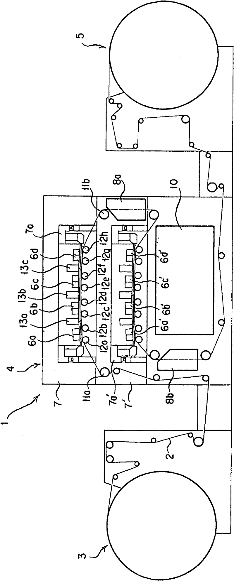
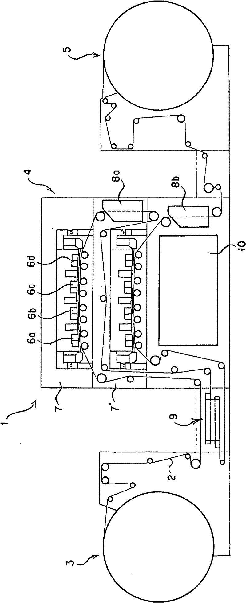
[0029] figure 1 The inkjet recording apparatus 1 according to the first embodiment of the present invention is schematically shown, and the inkjet recording apparatus 1 prints on the paper 2 supplied from the paper supply section 3 by the inkjet head. The inkjet printing unit 4 and the take-up unit 5 for winding the paper 2 printed by the inkjet printing unit 4 are constituted.

[0030] As the above-mentioned inkjet printing unit 4, it has a structure in which first and second printing units 7, 7' are superimposed on each other in the vertical direction. A plurality of, for example, four (Y, M, C, K) inkjet heads 6a, 6b, 6c, 6d and 6a', 6b', 6c', 6d' are arranged.

[0031] Moreover, in the first embodiment of the present invention, when the paper feeding direction of the paper 2 fed from the paper feeding unit 3 is referred to as the “forward direction” and the opposite direction is referred to as the “reverse direction”, the direction from the paper feeding unit 3 is The su...


PUM


Abstract

Disclosed is an inkjet recorder which ensures good print quality by minimizing flapping of a sheet which travels in parallel with the nozzle width region of an ink jet head while facing the nozzle width region. An inkjet recorder is equipped with an inkjet print section (4) having print units (7, 7') for printing on a sheet (2) traveling on an arcuate sheet passage formed of a plurality of guide rollers (12a-12h) by means of a plurality of inkjet heads (6a-6d, 6a'-6d'), wherein an on-demand inkjet head equipped with a plurality of nozzle arrays in the traveling direction of sheet as a nozzle width region is used as the inkjet head of the print unit, the sheet passage opposite to the nozzle surface of each inkjet head is constituted of two guide rollers (12a, 12b) disposed on the upstream side and downstream side in the traveling direction of sheet, and the end portions of a sheet in the nozzle width region (L) of each inkjet head on the upstream side and downstream side in the traveling direction of sheet are located as closely as possible to each contact point between the guide rollers on the upstream side and downstream side on the inside of each contact point where the sheet touches the guide rollers, respectively, and being wound therearound.

Description

technical field [0001] The present invention relates to an inkjet head that uses ink ejection to print (print) onto paper, and more particularly to a nozzle row having a plurality of inkjet nozzles arranged in a width direction of the paper in the traveling direction of the paper. An inkjet recording device having an on-demand type inkjet head having a width in a paper traveling direction. Background technique [0002] In such an inkjet recording device, maintaining a constant gap between the inkjet head and the paper surface (printing surface) is an important element in order to obtain good printing quality. Inkjet recording device: regardless of the length of the roller distance between the rollers that guide the paper traveling opposite to the above-mentioned inkjet head, printing can be performed in a state where the paper does not flutter, and it is equipped with multiple rows of nozzles in the direction of paper travel. A row of inkjet heads performs high-precision pr...

Claims


Application Information

Patent Timeline
Patent Type & Authority Applications(China)
IPC IPC(8): B41J2/185B41J2/18B41J15/06B41J11/04B41J2/01
CPCB41J2/155B41J2/1714B41J2202/19B41J29/377B41J2202/20B41J3/543B41J3/60B41J11/0045B41J25/003B41J11/007
Inventor 井泽秀男并木孝夫石川晃山崎祐一
Owner MIYAKOSHI PRINTING MACHINERY
Why Eureka
Try Eureka