Fixing fool-proof jig for feed trays

A technology for feeding trays and jigs, applied in rigid containers, containers, packaging, etc., can solve the problems of polarity reversal and movement of the tray 5, and achieve the effect of avoiding polarity reversal.

Inactive Publication Date: 2011-08-31
昶虹电子(苏州)有限公司
View PDF2 Cites 0 Cited by
  • Summary
  • Abstract
  • Description
  • Claims
  • Application Information

AI Technical Summary

Problems solved by technology

The method for fixing the tray 5 in the prior art is to use the magnet 8, but the fixing of the magnet 8 is easy to cause the tray 5 to move; at the same time, when the placement direction of the tray 5 is reversed, the IC / BGA can also be placed on it, thereby cause its polarity to be reversed

Method used


Image

  • Fixing fool-proof jig for feed trays
  • Fixing fool-proof jig for feed trays
  • Fixing fool-proof jig for feed trays

Examples


Embodiment Construction

[0017] The present invention will be further described below in conjunction with accompanying drawing and embodiment:

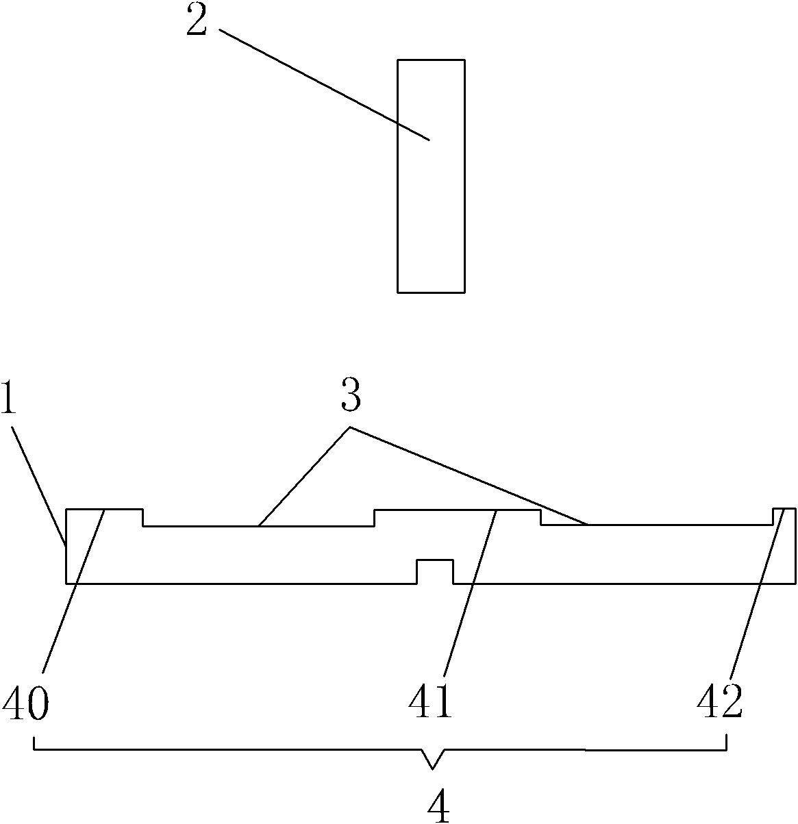
[0018] Such as figure 1 A fool-proof jig for fixing a feeding tray is shown, and the jig includes two parts: a first fixing part 1 and a second fixing part 2 . in:

[0019] One side of the first fixture 1 has a plurality of recesses 3 and protrusions 4 that are arranged at intervals. The widths of the convex sides 50 of the 5 are matched, and the widths of the convex parts 4 at both ends are unequal. In this embodiment: there are three convex portions 4, namely the first convex portion 40, the second convex portion 41, and the third convex portion 42. The width of the first convex portion 40 is equal to the width of the tray 5L1, and the width of the second convex portion 40 is equal to the width of the tray 5L1. The width of the three convex parts 42 is equal to the width of the tray 5L2, and there are two recesses 3, that is, two trays 5 can be fixed. ...


PUM


Abstract

The invention relates to a fixing fool-proof jig for feed trays. The jig is used for fixing two or more support trays; the side edge of each support tray is provided with a convex edge protruding towards the outer side; the jig comprises a first fixing element; one side of the first fixing element is provided with a plurality of recesses and bumps arranged at intervals; the two end parts of the recesses and bumps arranged at intervals are bumps; the width of each recess is matched with that of the convex edge of each support tray; and the widths of the bumps at the two ends are unequal. The recesses are combined with the bumps, and the recesses are used for fixing the convex edges of the support trays, so that the support trays are prevented from moving; and due to the adoption of the bumps with unequal widths at the two ends, the placement positions of the support trays can be prevented from being reversed, and the polarities of an IC / BGA (Integrated Circuit / Ball Grid Array) are prevented from being reversed during loading.

Description

technical field [0001] The invention relates to the field of processing printed circuit boards, in particular to a material feeding and fixing anti-fooling jig for placing printed circuit boards. Background technique [0002] At present, when packaging IC / BGA (PCB with Ball Grid Array structure), the feeding polarity of IC / BGA cannot be reversed, and the method of controlling whether the polarity is correct or not is realized through the tray. [0003] Such as figure 2 , 3 In the shown tray 5, the side portion of the tray 5 has a protruding flange 50 outward, and the flange 50 is not arranged in the middle of the side portion of the tray 5, that is to say The distance from the flange 50 to the two sides of the tray 5 is not the same: that is, L1 is not equal to L2. The method for fixing the tray 5 in the prior art is to use the magnet 8, but the fixing of the magnet 8 is easy to cause the tray 5 to move; at the same time, when the placement direction of the tray 5 is reve...

Claims


Application Information

Patent Timeline
IPC IPC(8): B65D79/02B65D19/38B65D85/86
Inventor 余勇才
Owner 昶虹电子(苏州)有限公司
Why Eureka
Try Eureka