
Liquid crystal display device

A technology of liquid crystal display devices and liquid crystal units, which is applied in the direction of identification devices, instruments, coatings, etc., can solve the problems of darkening of the screen, inability to recognize, and high cost, and achieve the effect of reducing coloring and ensuring visibility

Inactive Publication Date: 2011-08-17
SHARP KK
View PDF9 Cites 8 Cited by
  • Summary
  • Abstract
  • Description
  • Claims
  • Application Information

AI Technical Summary

Problems solved by technology

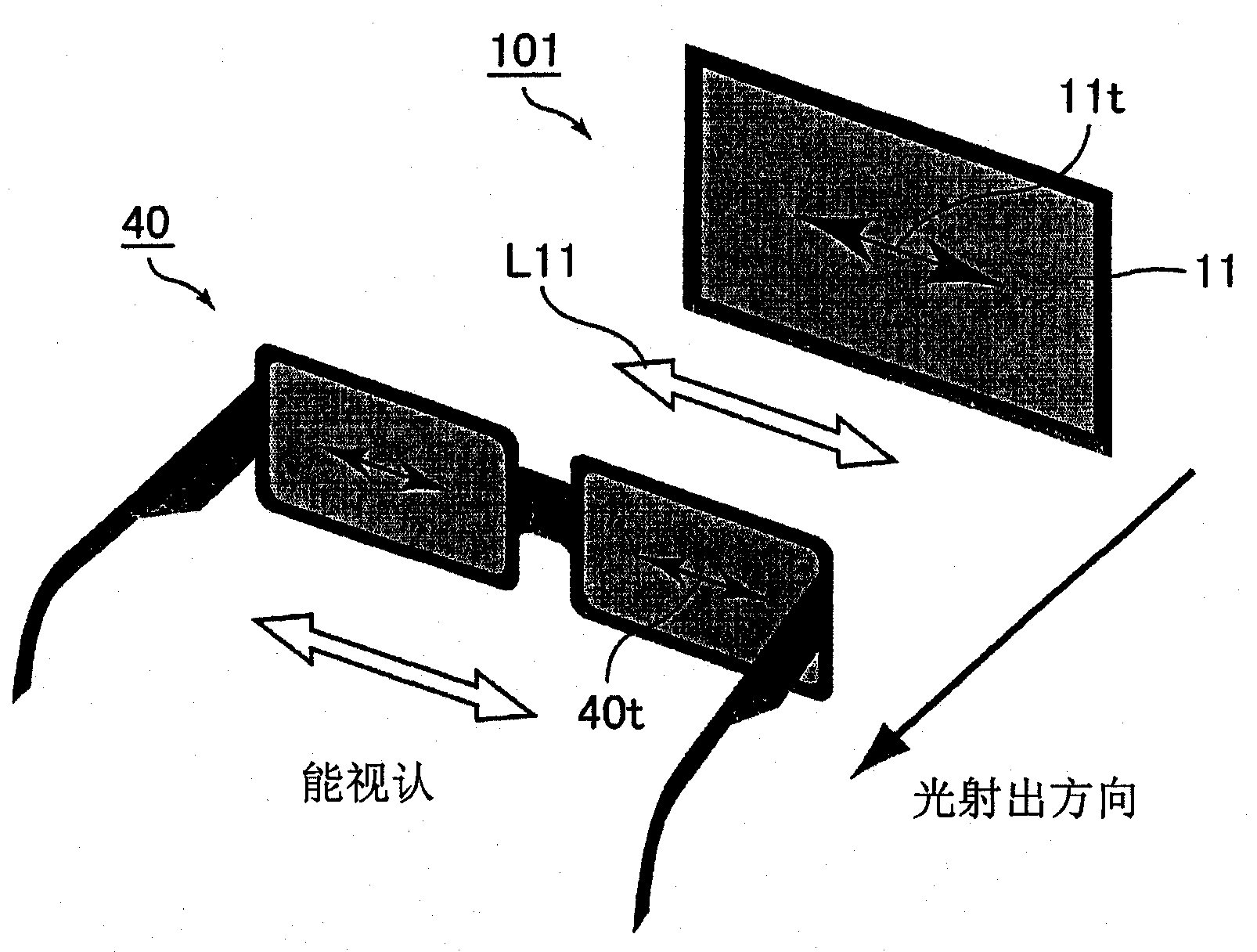
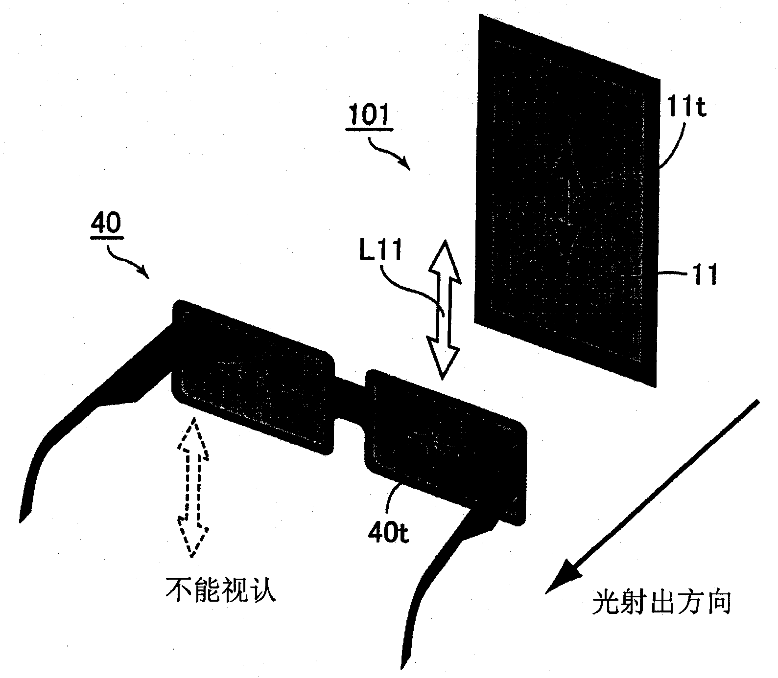
At this time, when the liquid crystal display device in which the polarization axis (absorption axis) of the polarizer on the front side is set in the longitudinal direction of the screen is installed in the portrait mode as it is, the screen becomes dark and becomes dark as described above. cannot be recognized
In addition, it is conceivable to prepare two kinds of polarizers for landscape mode and polarizer for portrait mode, and stick them separately according to the respective installation methods, but this method is expensive

Method used


Image

  • Liquid crystal display device
  • Liquid crystal display device
  • Liquid crystal display device

Examples


Embodiment approach 1

[0052] (Liquid crystal display device)

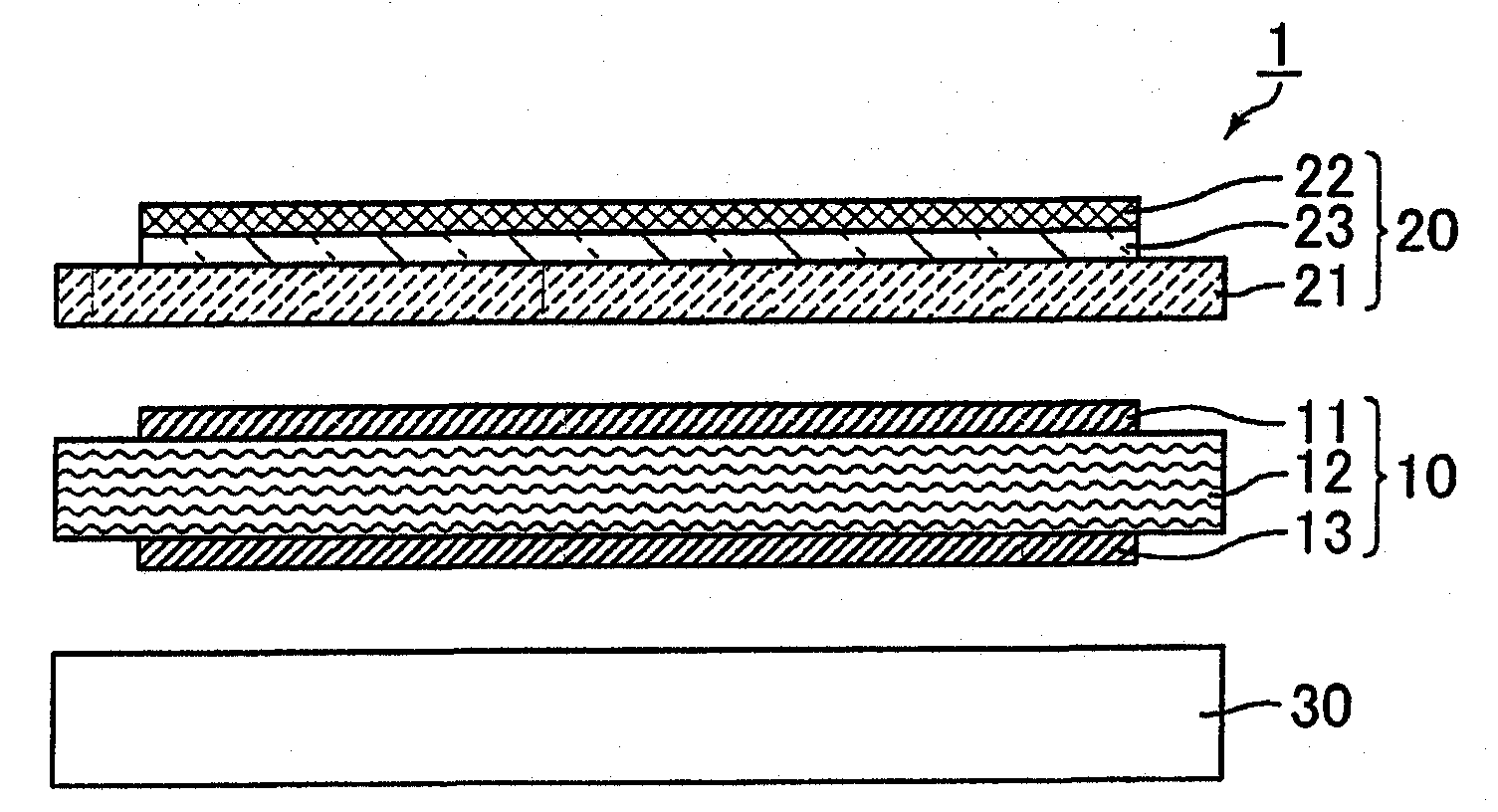
[0053] The liquid crystal display device 1 of this embodiment is as figure 1 As shown, a transmissive liquid crystal display device is provided with a backlight unit 30, a liquid crystal display panel 10 provided on the light-emitting surface side of the backlight unit 30, and a front panel 20 provided on the observation surface side of the liquid crystal display panel 10.

[0054] The liquid crystal display panel 10 has a liquid crystal cell 12, a polarizing element 11 (corresponding to the above-mentioned first polarizing element) adhered with an acrylic adhesive material on the observation surface of the liquid crystal cell 12, and an acrylic adhesive on the back of the liquid crystal cell 12 The polarizing element 13 (corresponding to the aforementioned third polarizing element) to which the material is attached.

[0055] The front panel 20 has a protective plate 21, an optically anisotropic layer 23 adhered by an acrylic adhesive materia...

Embodiment 1

[0122] (Production of 1 / 4 wavelength plate)

[0123] A long cyclic polyolefin resin film (produced by Japan Sonon Co., Ltd., trade name "ゼオノアフイルム") was uniaxially stretched at a temperature of 140°C between rolls with different peripheral speeds at 1.52 times to produce a long strip Shaped retardation film (1 / 4 wavelength plate). The thickness of this film is 35 μm, and the in-plane retardation Re is 139 nm.

[0124] (Making of the front panel)

[0125] The obtained quarter-wave plate was bonded to a commercially available polarizing plate (manufactured by Nitto Denko Corporation, trade name "SEG1224DU") via an adhesive layer. At this time, the angle formed by the slow axis of the quarter-wavelength plate and the absorption axis of the polarizer is set to 45°. In addition, this polarizing plate has a structure in which an iodine-based polarizing film is sandwiched by two TACs.

[0126] The obtained polarizing plate with 1 / 4 wavelength plate was bonded to a certain glass substrate a...


PUM


Abstract

Provided is a liquid crystal display which makes it possible to ensure visibility and decrease colouring irrespective of the orientation of a screen, even when the screen is viewed through an optical member having a polarizing effect such as polarizing sunglasses. The liquid crystal display device is provided with a liquid crystal cell and a first polarizing element disposed at the observation surface side of the liquid crystal cell, and the liquid crystal display device is further provided with a second polarizing element disposed at the observation surface side of the first polarizing element. The liquid crystal display device is preferably further provided with a protective plate disposed between the first polarizing element and the second polarizing element.

Description

Technical field [0001] The present invention relates to a liquid crystal display device. In more detail, it relates to a liquid crystal display device suitable for visual recognition with polarized sunglasses attached. Background technique [0002] In recent years, large screens of liquid crystal display devices have been developed and applied to various applications such as large televisions. Among them, the use of a display device called a digital signage used in an external environment has attracted particular attention. [0003] For such liquid crystal display devices used in external environments, in order to avoid glare from external light, viewers sometimes perform visual recognition while wearing polarized sunglasses. A liquid crystal display device generally performs display using a polarizing element provided on the front side, and light passing through the polarizing element on the front side is emitted to the viewer's side. Therefore, the emitted light becomes linearl...

Claims


Application Information

Patent Timeline
Patent Type & Authority Applications(China)
IPC IPC(8): G02F1/1335G02B1/11G02B5/30G09F9/00G02B1/118G02B1/14G02F1/13363
CPCG02F1/133528G02F2001/133531G02F1/13363G02B5/30G02B1/118G02F2001/133638G02F1/133531G02F1/133638
Inventor 长谷川雅浩坂井彰
Owner SHARP KK
Learn More