Electric heater with omega tube

An electric heating device and heating element technology, applied in the direction of the shape of the heating element, can solve problems such as high cost, and achieve the effect of reliable heat distribution

Active Publication Date: 2011-08-17
TUERK & HILLINGER
View PDF7 Cites 4 Cited by
  • Summary
  • Abstract
  • Description
  • Claims
  • Application Information

AI Technical Summary

Problems solved by technology

But this is associated with high costs in the manufacturing process

Method used


Image

  • Electric heater with omega tube
  • Electric heater with omega tube

Examples


Embodiment Construction

[0033] In all figures, the same reference numerals are used for the same components of the same embodiment.

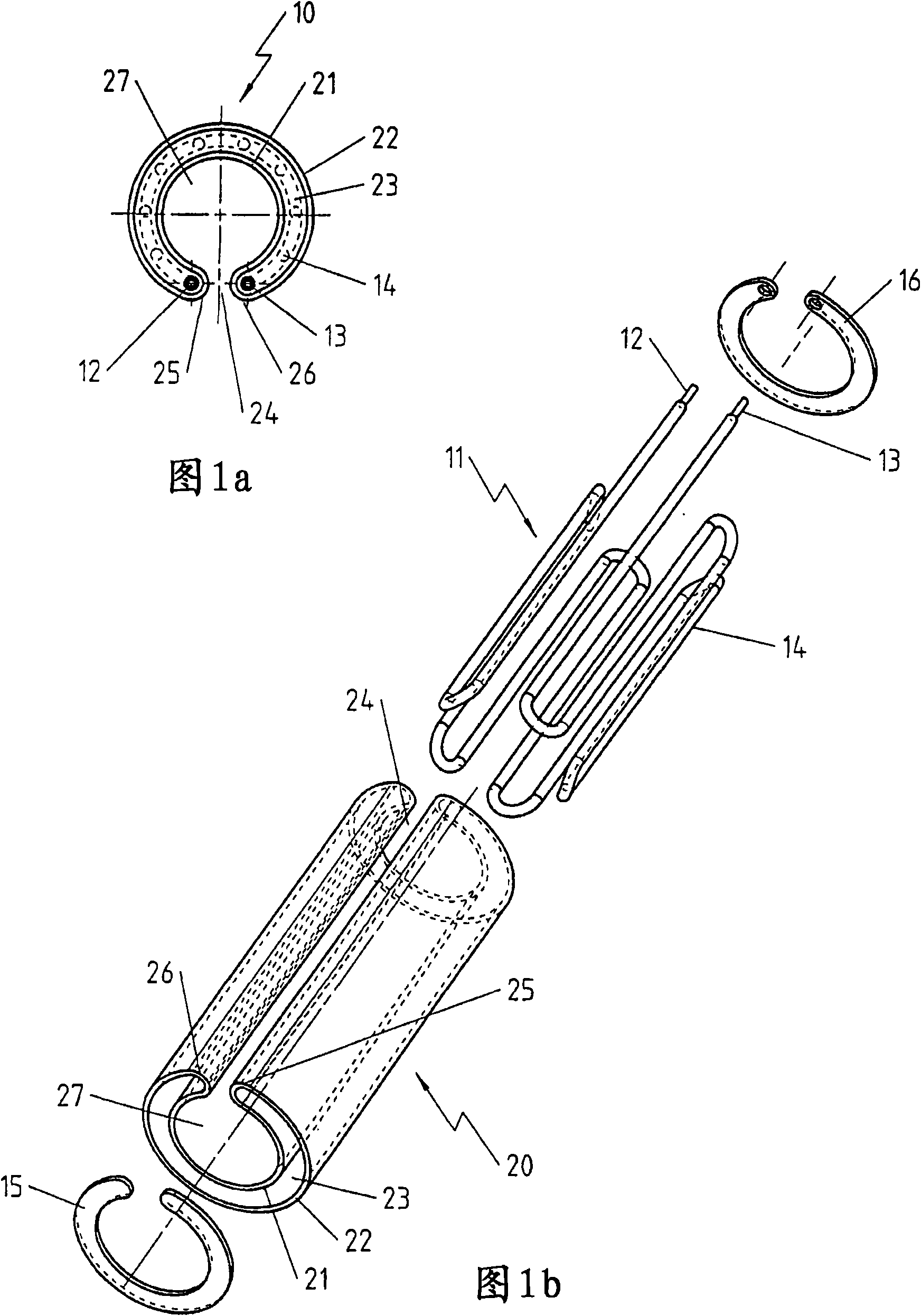
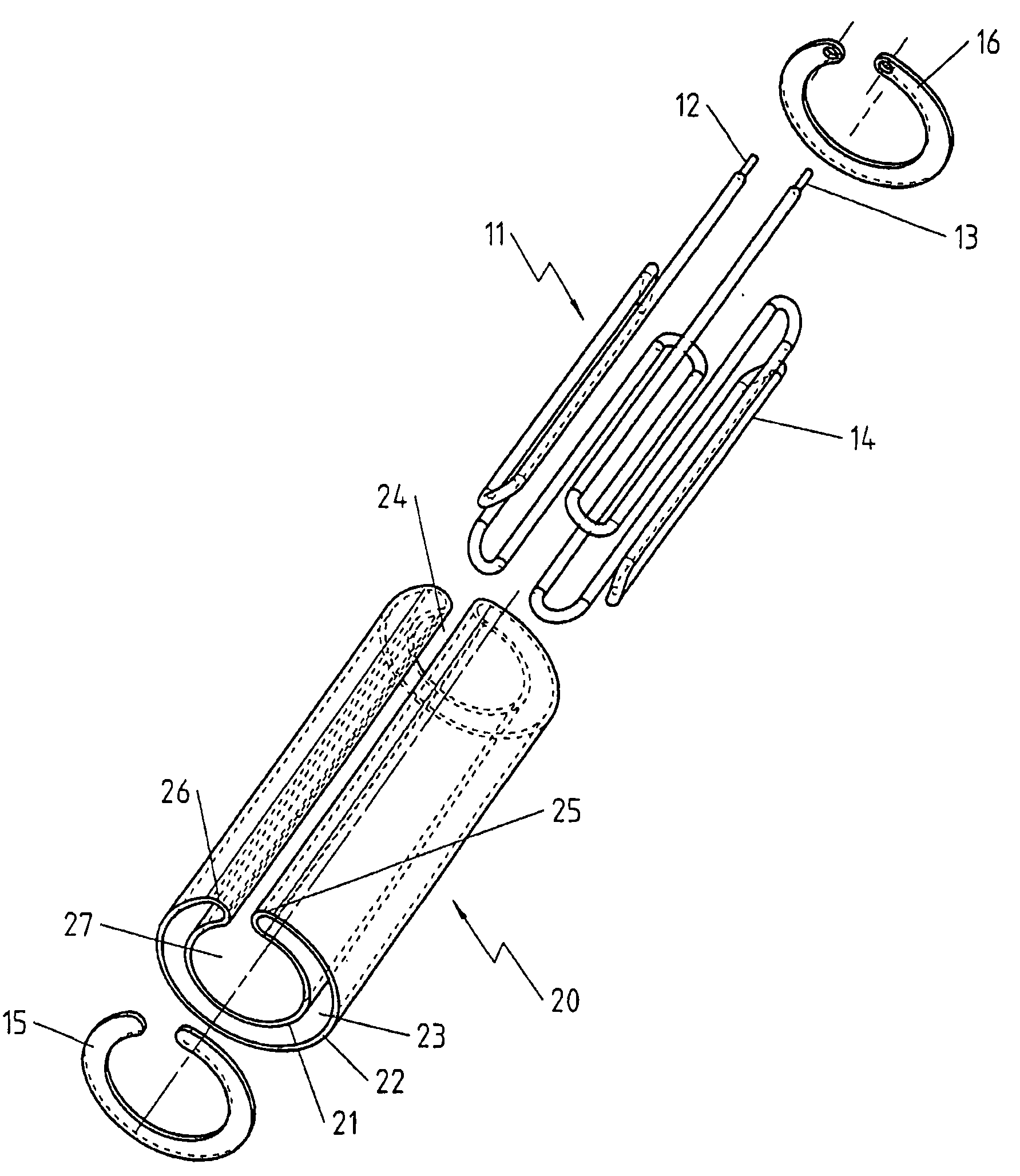
[0034] Figure 1a A sectional view of an electric heating device according to an embodiment of the present invention is shown (the section is perpendicular to the extending direction of the electric heating device). The electric heating device 10 has a double-walled tube 20 with an inner wall shell 21 and an outer wall shell 22 , between which a space 23 is defined. The inner wall shell 21 and the outer wall shell 22 are radially symmetrical in the section shown and are arranged coaxially with one another, but other geometries are also possible. The inner wall shell 21 and the outer wall shell 22 are penetrated by a gap 24 . Space 23 passes through walls 25, 26 (in Figure 1a The center is bent toward the gap 24) and the gap is spaced. The inner wall shell 21 and the part of the gap which passes through the inner wall shell 21 enclose a space 27 in which, for example...


PUM


Abstract

An electric heater (10), especially for heating surfaces of components, over which the electric heater (10) is pushed or on which it is placed, is provided with an inner jacket (21) and an outer jacket (22), which form a double-walled tube (20), wherein said double-walled tube (20) has a recess (24), which passes completely through the inner jacket (21) and the outer jacket (22), in the direction in which the electric heater (10) extends, and which is delimited by wall surfaces (25, 26) from the space (23) between the inner jacket (21) and outer jacket (22). The heater (10) has at least one tubular heating element (11), which has a metal jacket, and which is arranged in the space (23) between the inner jacket (21) and outer jacket (22). The inner jacket (21), the outer jacket (22) and the wall surfaces (25, 26) are contiguous and are formed of a single piece of material.

Description

technical field [0001] The invention relates to an electric heating device having the features of the preamble of claim 1 . Heating devices of this type are used, for example, for heating tools, machine parts and devices, especially plastic nozzles. However, its use is not limited thereto, for example, the liquid can also be brought to a desired temperature after passing through such a heating device. It is also optional to bring the static liquid or expanding wax to the desired temperature. Background technique [0002] A particularly common embodiment of such a heating device is cylindrical. In contrast, cylindrical heating devices are known, for example, from DE 20109413U1, EP 1395085B1 or DE 10333206B4. [0003] These known electric heating devices generally consist of two interfaces (in particular tubes) arranged at a distance from one another, between which a generally tubular heating element containing the actual heating conductor is arranged. There are also const...

Claims


Application Information

Patent Timeline
Patent Type & Authority Applications(China)
IPC IPC(8): H05B3/48B29C45/72
CPCH05B3/48B29C45/74B29C45/2737Y10T29/49826
Inventor A·施利普夫
Owner TUERK & HILLINGER
Why Eureka
Try Eureka