
Solar photovoltaic system and fault detection method thereof

A solar photovoltaic and fault technology, applied in the field of solar photovoltaic technology, can solve problems such as cable disconnection, detection of current and voltage, failure to detect system faults in time, and system failure, so as to shorten the time of fault impact, eliminate the threat of electric shock, and ensure personal safety. safe effect

Active Publication Date: 2013-04-17
ALTENERGY POWER SYST
View PDF3 Cites 0 Cited by
  • Summary
  • Abstract
  • Description
  • Claims
  • Application Information

AI Technical Summary

Problems solved by technology

[0003] In the current solar photovoltaic system, when it is necessary to maintain or approach the system (such as routine maintenance, fire fighting), even if the grid-connected switch is disconnected, if the photovoltaic module is still working, it will generate high voltage, which will pose a threat to personal safety. threaten
[0004] When someone steals the components of the solar photovoltaic system at night, since the photovoltaic modules do not generate current or voltage, the usual methods of detecting current and voltage cannot detect system failures in time, and then take protective measures
Similarly, if a system failure occurs at night, such as a disconnection of a cable connection, it cannot be detected in time

Method used


Image

  • Solar photovoltaic system and fault detection method thereof
  • Solar photovoltaic system and fault detection method thereof
  • Solar photovoltaic system and fault detection method thereof

Examples


Embodiment Construction

[0064] The present invention will be further described below in conjunction with specific embodiments and accompanying drawings, but the protection scope of the present invention should not be limited thereby.

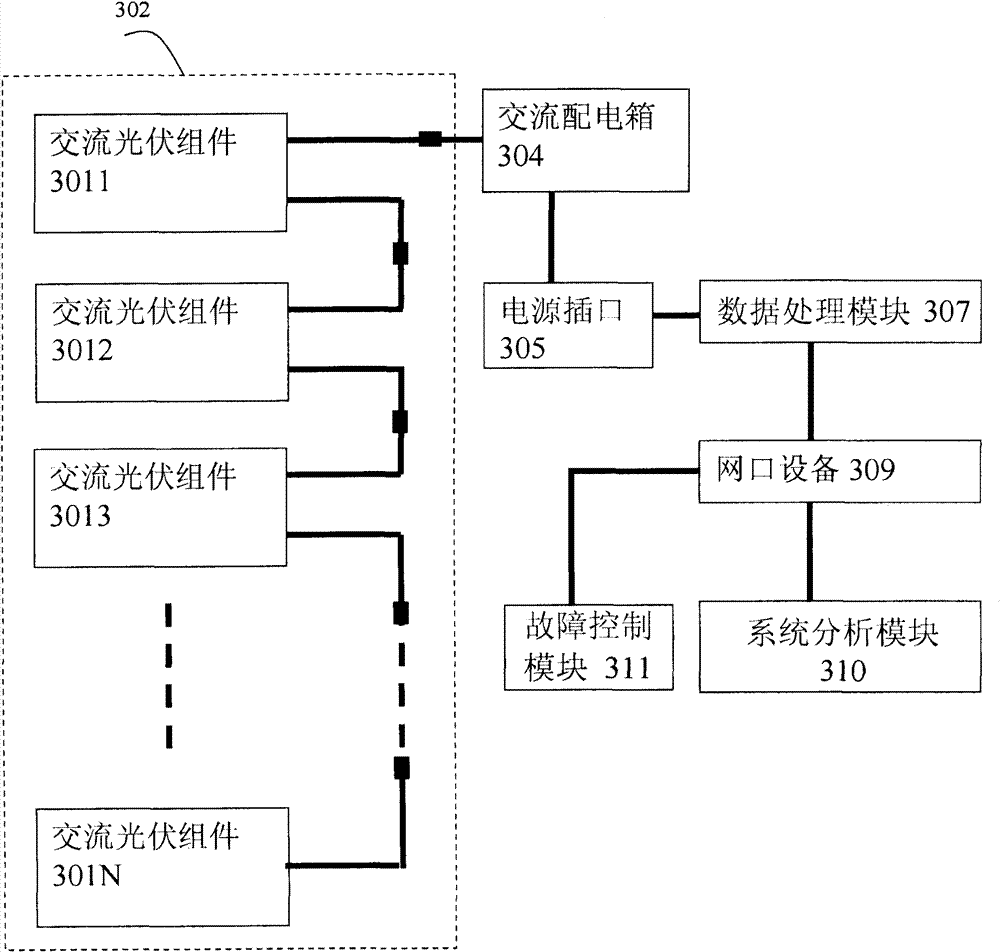
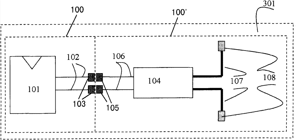
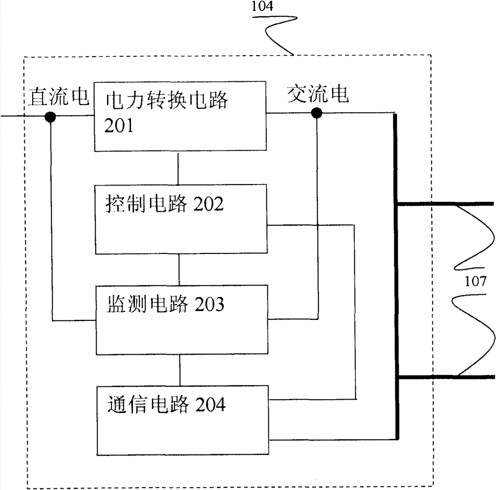
[0065] figure 1 It is a schematic structural diagram of a solar photovoltaic system according to an embodiment of the present invention. As shown in the figure, the solar photovoltaic system may include:

[0066] A plurality of AC photovoltaic modules 3011, 3012, 3013...301N are connected in series with each other to form an AC photovoltaic module string 302 for generating alternating current according to solar energy;

[0067] The data processing module 307 is sequentially connected to the AC photovoltaic module string 302 through the power socket 305 and the AC distribution box 304, and is used to communicate with each AC photovoltaic module 3011, 3012, 3013...301N through the power line communication technology, and obtain each The power parameters of AC photovolta...


PUM


Abstract

The invention provides a solar photovoltaic system, which comprises a plurality of alternating current photovoltaic components, a data processing module and a system analysis module, wherein the plurality of alternating current photovoltaic components are mutually connected in series for constituting an alternating current photovoltaic component string to generate alternating current according tosolar energy; the data processing module is connected with the alternating current photovoltaic component string and used for acquiring power parameters of all the alternating current photovoltaic components through power line communication technology and detecting and identifying abnormality or a fault in the solar photovoltaic system; and the system analysis module is connected with the data processing module and used for collecting system data from the data processing module and storing, analizing, drawing or displaying the system data. The invention further provides a fault detection method of the solar photovoltaic system. Through the way of monitoring real-time data transmission between all the alternating current photovoltaic components and the data processing module, when the fault occurs in the photovoltaic system, the generation of the fault can be timely detected, and the position and the type of the fault can be further identified, thereby enabling maintenance staff to repair the fault as soon as possible and reducing the impacts on normal power generation.

Description

technical field [0001] The invention relates to the field of solar photovoltaic technology, in particular, the invention relates to a solar photovoltaic system and a fault detection method thereof. Background technique [0002] Existing solar photovoltaic systems generally include at least: DC photovoltaic modules, used to generate DC power; module inverters, used to convert DC power into AC power; module interfaces, used to receive DC power from DC photovoltaic modules; wires; Used to receive AC power from other modules or connect to the AC power grid; communication lines are used to transmit data and control signals, etc. [0003] In the current solar photovoltaic system, when it is necessary to maintain or approach the system (such as routine maintenance, fire fighting), even if the grid-connected switch is disconnected, if the photovoltaic module is still working, it will generate high voltage, which will pose a threat to personal safety. threaten. [0004] When someon...

Claims


Application Information

Patent Timeline
Patent Type & Authority Patents(China)
IPC IPC(8): H02N6/00G01R31/26H02S10/00H02S50/00
CPCY02E10/50
Inventor 罗宇浩凌志敏
Owner ALTENERGY POWER SYST
Learn More