Vibratory feeding machine

A technology of vibrating feeder and feeding trough, which is applied in vibrating conveyors, conveyors, transportation and packaging, etc., which can solve the problems of large equipment volume and weight, short service life, and large motor power

Inactive Publication Date: 2011-07-06
HENAN TAIHANG VIBRATING MACHINERY
View PDF0 Cites 4 Cited by
  • Summary
  • Abstract
  • Description
  • Claims
  • Application Information

AI Technical Summary

Problems solved by technology

The disadvantages are that the motor and the reducer directly participate in the vibration, which makes the equipment bulky and heavy, requires a large motor power, high energy consumption, and the amplitude adjustment is inconvenient and the service life is short

Method used


Image

  • Vibratory feeding machine
  • Vibratory feeding machine
  • Vibratory feeding machine

Examples


Embodiment Construction

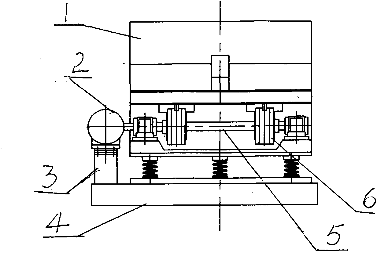
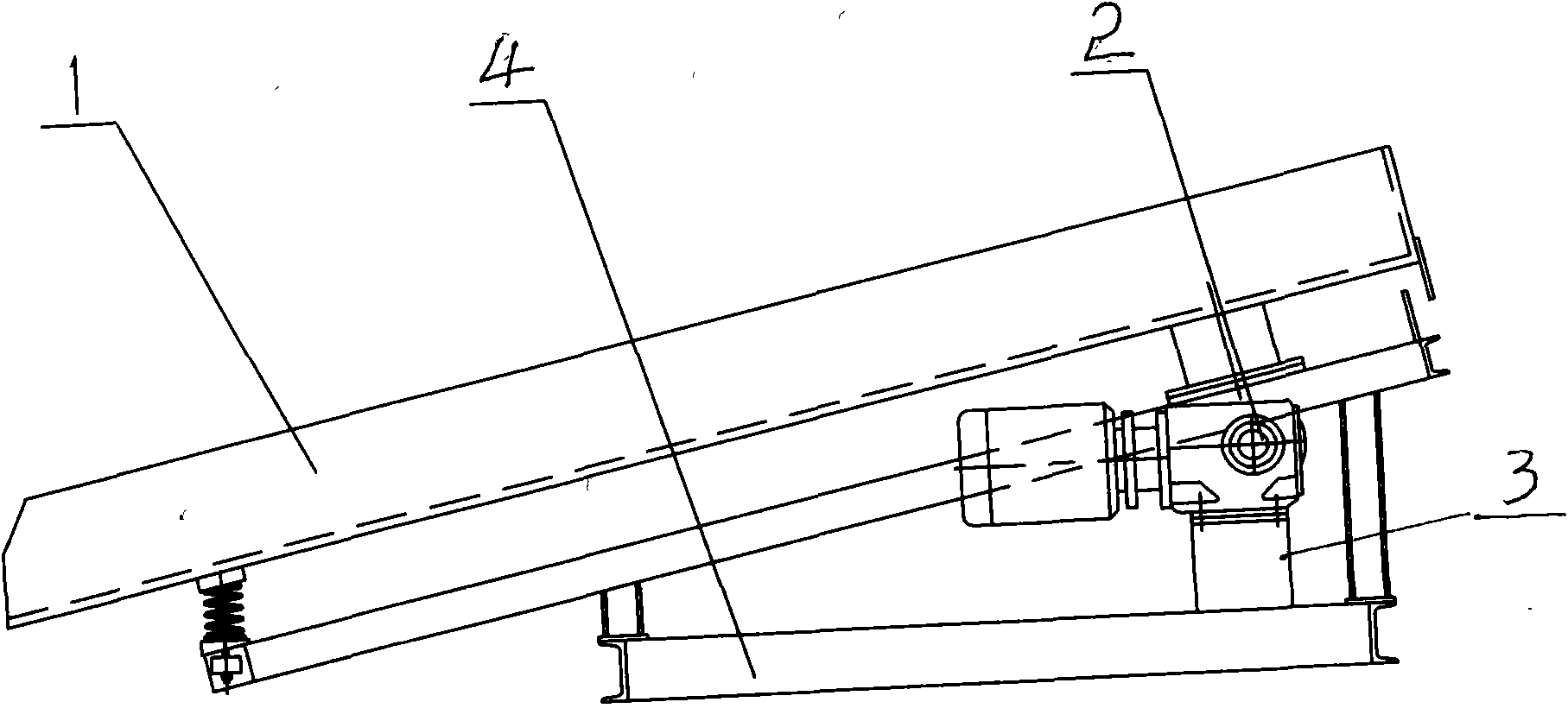
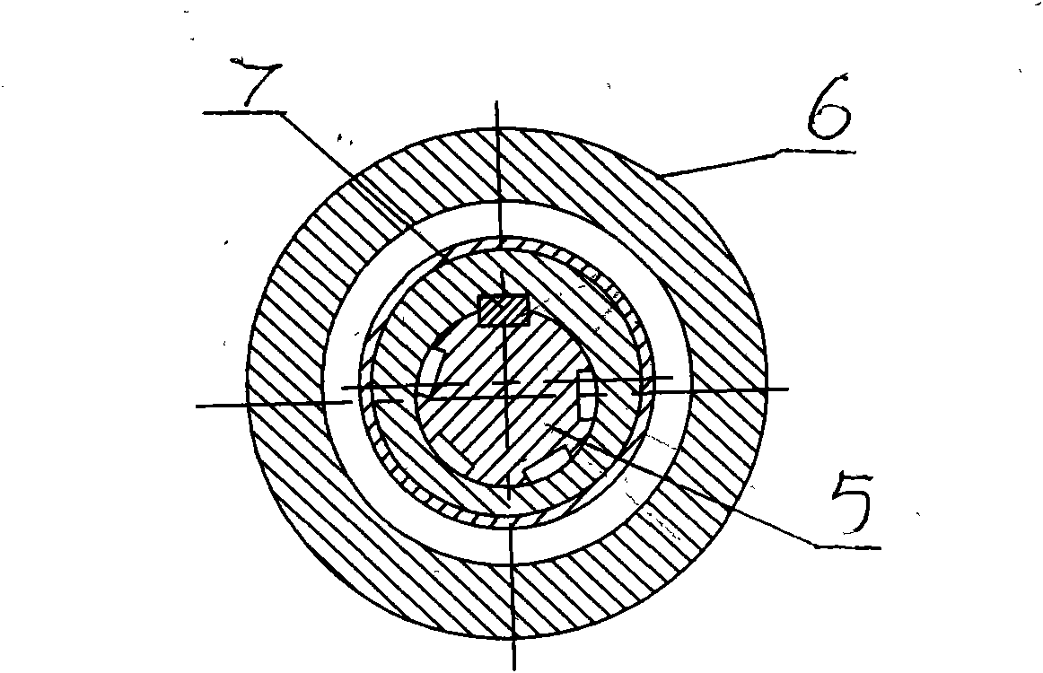
[0006] Embodiments are described in detail with reference to the accompanying drawings. The present invention is an improvement on the prior art, and it includes a feeding trough 1 and its vibration-damping frame 4. The improvement is that a motor base 3 is provided on one side of the feeding trough, and a speed reducer is installed on the motor base. Machine 2, a spline shaft 5 is installed on both sides of the vibration damping frame at the bottom of the feeding trough through the bearing seat, and two vibrators 6 are symmetrically installed on the spline shaft, and one end of the spline shaft is connected to the reducer shaft on (such as figure 1 shown). During use, by adjusting the installation orientation of the key 7 on the spline shaft, the size of the amplitude can be adjusted conveniently.


PUM


Abstract

The invention discloses a vibratory feeding machine which comprises a feed trough and a vibration-absorbing frame, wherein a motor holder is arranged on one side of the feed trough, a speed reducer is mounted on the motor holder, a splined shaft is mounted through bearing supports on two sides of the bottom part of the feed trough and above the vibration-absorbing frame, two vibrators are symmetrically mounted on the splined shaft, and one end of the splined shaft is connected onto a shaft of the speed reducer. The speed reducer is mounted outside the feed trough, so as to reduce the weights of the components responsible for vibration, reduce the power and the energy consumption, provide great convenience for repair and maintenance and help prolong the service life. Besides, the amplitude of vibration is conveniently adjusted by adjusting the mounting position of a key on the splined shaft.

Description

Technical field: [0001] The invention relates to conveying equipment, in particular to a vibrating feeder with small required motor power, convenient amplitude adjustment, convenient maintenance and long service life. Background technique: [0002] Present vibrating feeder, mostly all is that vibrating motor is installed on the conveying trough body of vibrating feeder, and conveying chute is installed on a vibration-damping chassis. The disadvantages are that the motor and the reducer directly participate in the vibration, which makes the equipment bulky and heavy, requires a large motor power, high energy consumption, and it is inconvenient to adjust the amplitude and has a short service life. Invention content: [0003] The object of the present invention is to provide a vibrating feeder with simple structure, low energy consumption, convenient amplitude adjustment and long service life. [0004] The technical solution of the present invention is accomplished in the fo...

Claims


Application Information

Patent Timeline
IPC IPC(8): B65G27/32B65G27/18
Inventor 黄全青王翠梅
Owner HENAN TAIHANG VIBRATING MACHINERY
Why Eureka
Try Eureka