Cutting tool

A technology of cutting tool and fixed blade, applied in metal processing and other directions, can solve the problems of inconvenient use, cumbersome operation, complex cutting tool structure, etc., and achieve the effect of simplified structure and convenient operability

Active Publication Date: 2013-01-09
POSITEC POWER TOOLS (SUZHOU) CO LTD
View PDF1 Cites 0 Cited by
  • Summary
  • Abstract
  • Description
  • Claims
  • Application Information

AI Technical Summary

Problems solved by technology

[0004] However, the structure of the shearing tool is relatively complicated, and a connecting plate that can rotate relatively is provided in the connecting seat, and the movable blade needs to be connected with the connecting plate in advance, which is cumbersome to operate and inconvenient to use.

Method used


Image

  • Cutting tool
  • Cutting tool
  • Cutting tool

Examples


Embodiment Construction

[0046] The present invention will be further described in detail below in conjunction with the accompanying drawings and specific embodiments.

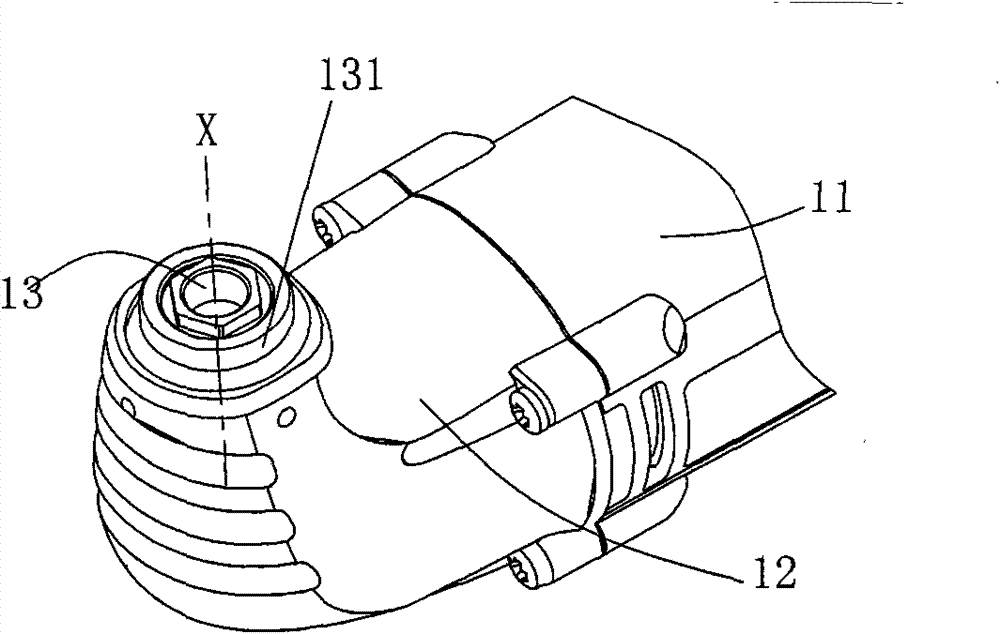
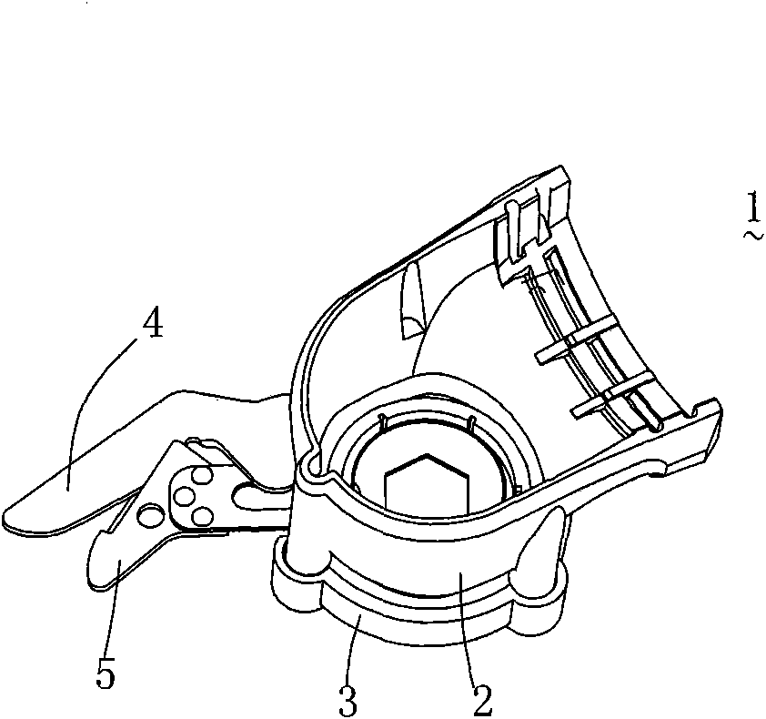
[0047] see figure 1 , a shearing tool 1 applied to an oscillating power tool, suitable for shearing operations. The oscillating power tool is designated as a reference numeral 10, and comprises a cylindrical casing 11 and is connected to the front end of the casing 11 ( figure 1 The left side of the middle is defined as the head shell 12 which is arranged roughly in an angular direction, and the output shaft 13 extends from the head shell 12 . Such as figure 2 As shown, the free end of the output shaft 13 is in the shape of a regular hexagon and has an axis X. An annular flange 131 is also formed radially at the free end of the output shaft 13 .

[0048] read on figure 1 A motor (not shown) that provides driving force and a transmission assembly (not shown) that transmits torque are arranged in the casing 11 of the swing power t...


PUM


Abstract

The invention relates to a cutting tool which is detachably connected to a handheld type swinging power tool. The swinging power tool comprises a head shell (12) and an output shaft (13) which has an axis and extends out from the head shell (12), wherein the output shaft (13) can swing around the axis. The cutting tool comprises a connecting base (2) connected to the head shell (12), a fixed blade (4) connected to the connecting base (2), a moveable blade (5) capable of moving relative to the fixed blade (4), and a sealing cover (3) which is fixed relative to the connecting base (2), wherein the moveable blade (5) is contained between the connecting base (2) and the sealing cover (3). By using the cutting tool provided by the invention, as the sealing cover is added and the moveable bladeis contained between the connecting base and the sealing cover, the structure needing a connecting plate of the prior art is simplified and the operation of fixing the moveable blade in advance is avoided, thereby bringing convenience to operation.

Description

technical field [0001] The invention relates to a shearing tool, in particular to a shearing tool detachably connected to a hand-held oscillating power tool. Background technique [0002] Chinese patent application CN200910127475.6 discloses a shearing tool. The shearing tool is detachably connected to a hand-held oscillating power tool, including a movable blade and a fixed blade, and a connecting seat for connecting a multi-kinetic machine. A connecting plate is arranged in the connecting seat, and the connecting plate can be relatively The connecting seat rotates relatively. Because the movable blade is also connected on the connecting plate, thereby it can rotate together thereupon, and the fixed blade is then fixedly connected on the connecting seat. [0003] When the shearing tool is connected to the oscillating power tool, the connection plate is connected with the output shaft of the oscillating power tool. Since the output shaft of the oscillating power tool is sw...

Claims


Application Information

Patent Timeline
Patent Type & Authority Patents(China)
IPC IPC(8): B26B15/00
Inventor 李祥庆张士松
Owner POSITEC POWER TOOLS (SUZHOU) CO LTD
Why Eureka
Try Eureka