
Method and device for monitoring and alarming residual current, and detection controller

A residual current, monitoring and alarming technology, used in electrical fire alarms, measuring current/voltage, instruments, etc., can solve problems such as false alarms, leakage alarms, etc., to avoid leakage alarms, false alarms, and residual current alarm thresholds reasonable effect

Inactive Publication Date: 2013-07-10
CHINA ACAD OF BUILDING RES +1
View PDF0 Cites 0 Cited by
  • Summary
  • Abstract
  • Description
  • Claims
  • Application Information

AI Technical Summary

Problems solved by technology

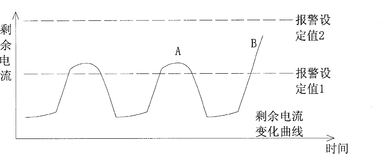
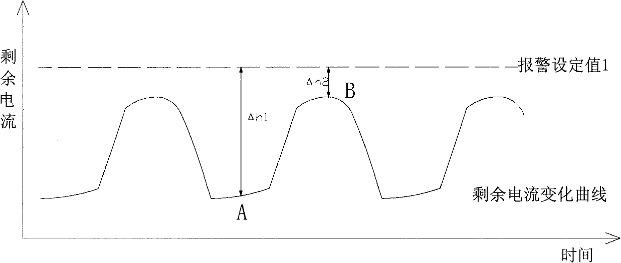
The method, device and system can dynamically determine the residual current alarm threshold, effectively solving the problems of missed alarms and false alarms caused by the use of fixed alarm thresholds in the prior art

Method used


Image

  • Method and device for monitoring and alarming residual current, and detection controller
  • Method and device for monitoring and alarming residual current, and detection controller
  • Method and device for monitoring and alarming residual current, and detection controller

Examples


Embodiment 1

[0026] This embodiment provides a residual current monitoring and alarming method, the purpose of which is to intelligentize the determination of the alarming threshold through the follow-up technology of the alarming threshold, and to make dynamic adjustments, thereby avoiding the residual current electrical fire monitoring system that uses a fixed alarming threshold. It can improve the reliability and accuracy of the alarm in essence.

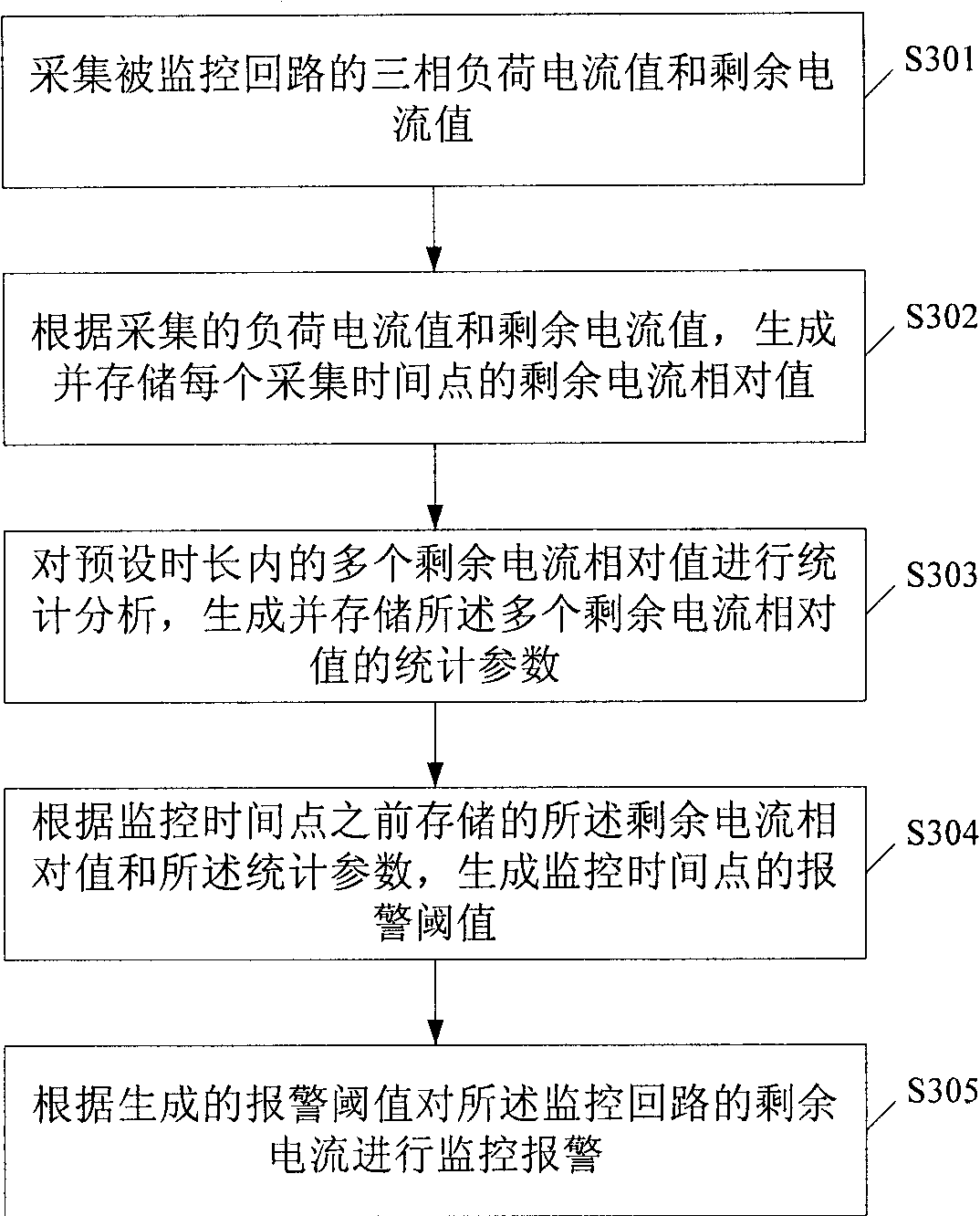
[0027] image 3 is the overall flowchart of the method. Such as figure 1 As shown, the method of the present embodiment includes:

[0028] S301. Collect the three-phase load current value and residual current value of the monitored circuit.

[0029] S302. Generate and store a relative value of residual current at each collection time point according to the collected load current value and residual current value.

[0030] Optionally, the relative value of the residual current in this embodiment is a ratio of the residual current value at t...

Embodiment 2

[0109] This embodiment provides a residual current monitoring and alarm system and a detection controller, Figure 6 It is the system schematic diagram of this embodiment. Such as Figure 6 As shown, the system of this embodiment includes: a centralized controller, a bus isolator, a detection controller, a current detector and a residual current detector; the centralized controller is connected to the detection controller through the bus isolator; the detection controller is connected to the current detectors and residual current detectors.

[0110] Among them: the current detector in this embodiment is used to collect the three-phase load current; the residual current detector is used to collect the residual current; the detection controller is used to generate and store each relative values ​​of residual current at each collection time point; perform statistical analysis on a plurality of relative values ​​of residual current within a preset period of time, generate and st...


PUM


Abstract

The invention provides a method and a device for monitoring and alarming residual current, and a detection controller. The method comprises the following steps of: acquiring a three-phase load current value and a residual current value of a monitored loop; generating and storing the residual current relative value of each acquisition time point according to the acquired load current value and residual current value; performing statistical analysis on a plurality of residual current relative values in a preset time interval, and generating and storing the statistical parameters of the plurality of residual current relative values; generating an alarm threshold value of a monitoring time point according to the residual current relative values and the statistical parameters which are stored before the monitoring time point; and monitoring and alarming the residual current of the monitored loop according to the generated alarm threshold value. By the method and the device for monitoring and alarming the residual current, and the detection controller, a leakage alarm and a false alarm caused by the conventional fixed alarm threshold value can be avoided.

Description

technical field [0001] The invention relates to the technical field of residual current electrical fire monitoring, in particular to a residual current monitoring and alarming method, system and detection controller. Background technique [0002] The residual current electrical fire monitoring system is a new product that has appeared in recent years. It is installed in the low-voltage power distribution system and its core function is to prevent electrical fires. In view of the serious situation of electrical fires in my country in the past ten years and the obvious improvement of fire prevention awareness in all sectors of society, the application of residual current electrical fire monitoring and alarm systems has developed very rapidly, especially in public buildings and high-rise buildings. The role of the residual current electrical fire monitoring system in preventing electrical fires has been gradually recognized by all parties, and has a very good application prospe...

Claims


Application Information

Patent Timeline
Patent Type & Authority Patents(China)
IPC IPC(8): G01R19/165G08B17/06
Inventor 李宏文沈金波张燕杰董卫国
Owner CHINA ACAD OF BUILDING RES
Learn More