


Quick Research
Generate reliable direction feasibility study reports for your R&D in just a few steps.

Technical Q&A
Discover and master advanced knowledge NOW. Basics, ideas, possibilities, all at once.

Find Solutions
As an expert in R&D theories, this can generate solutions to your technical problems instantly.

Evaluate Feasibility
Analyze your overall solution with one click, know your potential R&D risks in advance.

Monitor Landscape
Get weekly tech updates, stay abreast of the latest tech innovations and key insights.
Time-measurement device for applications without power source
A time measurement, device technology, used in card-like identification or authentication devices, in the field of electrical components of real-time clock circuits, to solve problems such as not being continuously connected to a power source
- Summary
- Abstract
- Description
- Claims
- Application Information
AI Technical Summary
Problems solved by technology
Method used
Image

Examples
Embodiment Construction
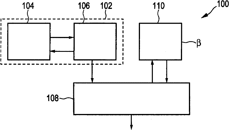
[0072] figure 1 A schematic simplified block diagram of a first embodiment of a time measuring device 100 is shown.
[0073] figure 1 The time measurement device 100 includes a timing reference circuit 102 . The timing reference circuit 102 has a MEMS resonator 104 . The structural details of the MEMS resonator will be further described below for illustrative examples. In general, such MEMS resonators are known in the prior art. The MEMS resonator 104 can be fabricated to provide specifications (regarding Q, frequency stability) equal or similar to those known from quartz resonators. MEMS resonators may be used in oscillator circuits such as oscillator circuit 106 to provide frequency stability and controllable oscillation frequencies in the range up to GHz.
[0074] Examples of suitable timing reference circuits connected to MEMS resonators are disclosed, for example, in WO 2008 / 033681A2, the entire content of which is incorporated herein. the document's figure 1 An...
PUM
 Abstract
Description
Claims
Application Information
 - R&D Engineer
- R&D Manager
- IP Professional
- Industry Leading Data Capabilities
- Powerful AI technology
- Patent DNA Extraction
Browse by: Latest US Patents, China's latest patents, Technical Efficacy Thesaurus, Application Domain, Technology Topic, Popular Technical Reports.
© 2024 PatSnap. All rights reserved.Legal|Privacy policy|Modern Slavery Act Transparency Statement|Sitemap|About US| Contact US: help@patsnap.com