Eureka AIR delivers breakthrough ideas for toughest innovation challenges, trusted by R&D personnel around the world.

Method for calculating propagation speed of earthquake waves in mine region by utilizing microearthquake point as earthquake source

A technology of propagation velocity and seismic waves, applied in the measurement of propagation velocity, seismology, geophysical measurement, etc., can solve problems such as impracticality, need, shutdown and production shutdown, space constraints, etc., to reduce production costs, improve safety, and facilitate mines effect of work

Inactive Publication Date: 2011-06-15
杨本才
View PDF5 Cites 12 Cited by
  • Summary
  • Abstract
  • Description
  • Claims
  • Application Information

AI Technical Summary

Problems solved by technology

This method needs to arrange exploration equipment in advance. In production mines, the arrangement of exploration equipment is not only limited by space, but also needs to stop work and production, which is very impractical for the mining process.
More importantly, it cannot be used for real-time monitoring
Therefore, although the propagation speed of seismic waves can effectively provide a large amount of information that is beneficial to mine safety production, it cannot be applied in the field

Method used


Image

  • Method for calculating propagation speed of earthquake waves in mine region by utilizing microearthquake point as earthquake source
  • Method for calculating propagation speed of earthquake waves in mine region by utilizing microearthquake point as earthquake source
  • Method for calculating propagation speed of earthquake waves in mine region by utilizing microearthquake point as earthquake source

Examples


Embodiment Construction

[0023] The present invention will be further described in detail below in conjunction with the accompanying drawings, so that those skilled in the art can implement it with reference to the description.

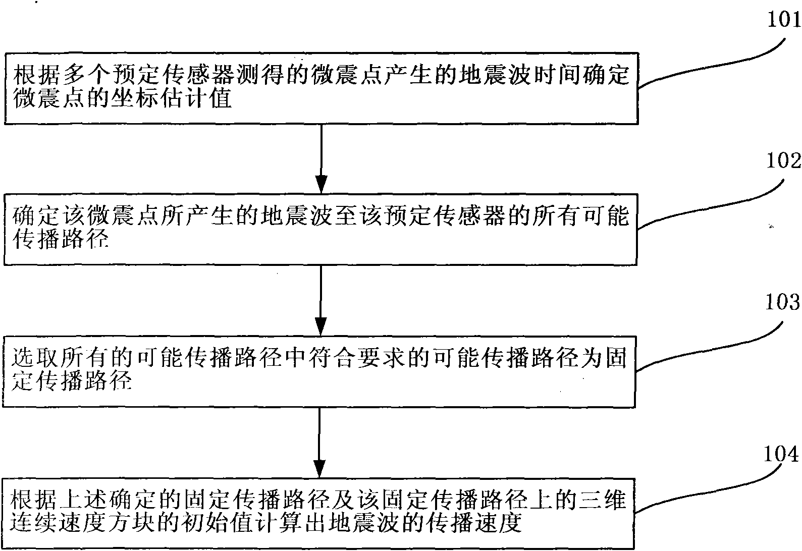
[0024] like figure 1 As shown, in the method for calculating the seismic wave propagation velocity in the mine area using the microseismic point as the seismic source according to the present invention, it is first necessary to divide the stratum of the mine area to be measured into different speeds according to the difference in the propagation velocity of the seismic wave in different strata in the mine area to be measured. Layers, such as coal seams, should be separated separately because their seismic wave propagation speed is different from that of surrounding rock formations. Separate interfaces are set between different speed layers, the upper part of the top speed layer, and the lower part of the bottom speed layer. like figure 2 As shown, each velocity layer is se...


PUM


Abstract

The invention discloses a method for calculating the propagation speed of earthquake waves in a mine region by utilizing a microearthquake point as an earthquake source, comprising the following steps: determining the coordinate estimated value of the microearthquake point according to the earthquake wave time generated by the microearthquake point measured by multiple preset sensors; determiningall possible propagation paths of the earthquake waves generated by the microearthquake point to the preset sensors according to the coordinate estimated value of the microearthquake point and the speed layer where the preset sensors are; selecting the possible propagation path with the difference between the earthquake wave propagation time and the earthquake wave time measured by the preset sensors corresponding to a preset range from all the possible propagation paths as a fixed propagation path; and calculating the propagation speed of the earthquake waves according to the determined fixed propagation path and the initial value of a three-dimensional continuous speed diamond on the fixed propagation path.

Description

technical field [0001] The invention relates to a calculation method for calculating the propagation speed of seismic waves, in particular to a method for calculating the propagation speed of seismic waves in mining areas by using microseismic points as seismic sources. Background technique [0002] The propagation velocity of seismic wave is one of the most effective on-site indicators to reflect the stress state of rock. [0003] The seismic wave propagation velocity of the local rock in the mining area increases with the increase of the stress. When the stress exceeds the bearing capacity of the rock, the rock will be destroyed rapidly, and the damaged rock will rapidly reduce the propagation speed of the seismic wave. More importantly, the propagation velocity of seismic waves is also an effective indicator to reflect the physical state of rocks. For example, when the rock is filled with gas or water, it will not only greatly reduce the propagation speed of the seismic...

Claims


Application Information

Patent Timeline
Patent Type & Authority Applications(China)
IPC IPC(8): G01V1/00G01H5/00
Inventor 杨本才
Owner 杨本才
Why Eureka
Eureka Blog
Learn More