
Floating connector

A connector and floating type technology, which is applied in the direction of connection, installation of connection parts, parts of connection devices, etc., can solve the problem of increasing the reachable range of floating components, and achieve the effect of avoiding damage

Active Publication Date: 2011-06-08
MOLEX INC
View PDF4 Cites 1 Cited by
  • Summary
  • Abstract
  • Description
  • Claims
  • Application Information

AI Technical Summary

Problems solved by technology

Therefore, the reachable range of the floating member is inevitably increased

Method used


Image

  • Floating connector
  • Floating connector
  • Floating connector

Examples


Embodiment Construction

[0038] While the invention is susceptible to embodiments in different forms, as shown in the drawings, and specific embodiments will be described with particular detail herein, it should be understood that this disclosure is to be considered as illustrative of the principles of the invention, and not It is intended to limit the invention to the examples described.

[0039] In the embodiments shown in the figures, the directional representations used to explain the structure and movement of the elements of the present invention, such as up, down, left, right, front, back, etc., are not absolute but relative . These representations are pertinent when the elements are in the positions shown in the figures. If the described location changes, these representations should change accordingly.

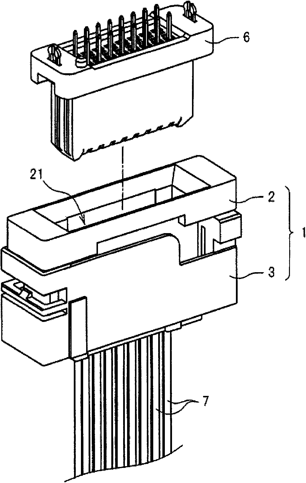
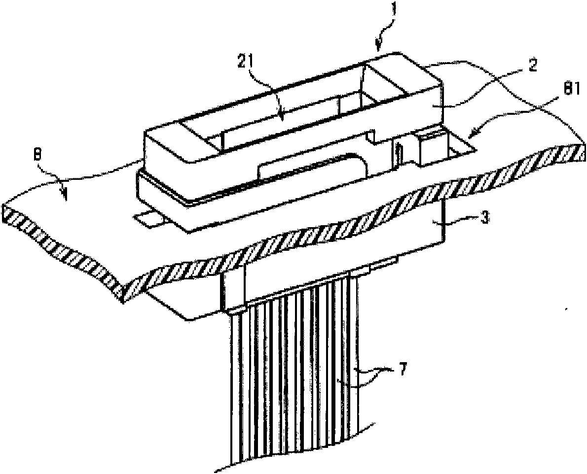
[0040] see Figure 1 to Figure 2 , shows that the floating connector 1 is installed on the panel 8 . In this embodiment, the vertical direction of the floating connector 1 corresponds to ...


PUM


Abstract

A floating connector (1) according to the present invention has a housing (2), and an adapter (3) having a through-hole (31) into which the housing (2) is inserted. The housing (2) includes: a first projection portion (27) that projects laterally outward and abuts against a periphery of an opening of the through-hole (31) to regulate a movement in an insertion direction; and a second projection portion (29) that is inserted into the through-hole (31) to regulate a movement in a direction opposite to the insertion direction with a stopper portion (39) which is disposed within the through-hole (31).

Description

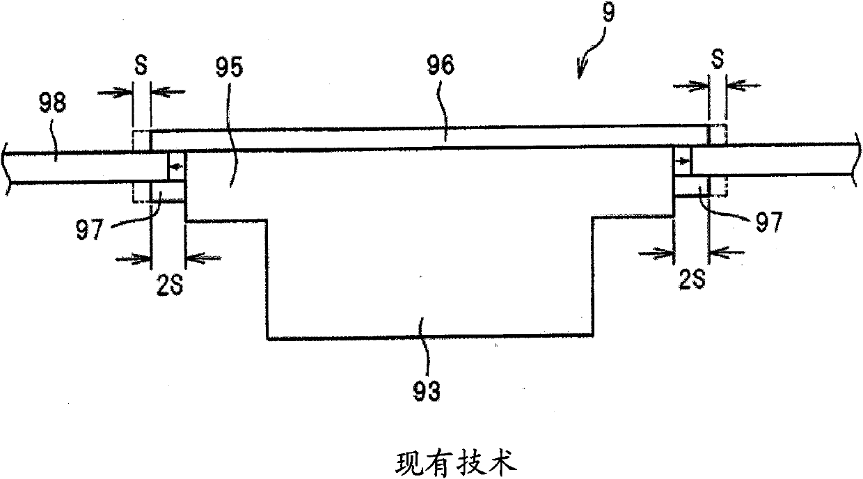
technical field [0001] The present invention relates generally to floating connectors, and more particularly to a two-piece floating connector capable of compressing the reach of a floating member. Background technique [0002] An example of a conventional floating type connector is disclosed in Japanese Utility Model Application Laid-Open No. Hei 7-18356, and is shown in FIG. 11b. Typically, conventional floating type connectors have a swivel portion, which is larger in diameter than the housing, disposed on the back side of the housing. The rotating portion is supported floatingly in a connector insertion hole formed in the panel. In addition, a leaf spring radially extends from the rotating part, and a fixed plate is provided on the back side of the rotating part. Finally, panels are sandwiched between these members to support the rotating part. [0003] However, in a conventional floating type connector, a leaf spring and a fixing plate are provided so that the rotati...

Claims


Application Information

Patent Timeline
Patent Type & Authority Applications(China)
IPC IPC(8): H01R13/631H01R13/74
CPCH01R13/6315H01R13/743
Inventor 小林康太郎松浦尚也
Owner MOLEX INC
Learn More