Once reciprocating reverse jacking type capsule de-molding machine

A technology of demolding machine and reciprocating mechanism, which is applied in the directions of capsule delivery, drug delivery, pharmaceutical formulation, etc., can solve the problems such as being unsuitable for large-scale production line matching, large body of the demolding machine, unfavorable for large-scale production line matching application, etc. Large-scale production line matching, compact and compact body

Inactive Publication Date: 2013-01-30
徐家业
View PDF4 Cites 0 Cited by
  • Summary
  • Abstract
  • Description
  • Claims
  • Application Information

AI Technical Summary

Problems solved by technology

[0002] The capsule demoulding machine of the prior art adopts a clamping plate for demoulding, and the clamping plate is provided with many clamping sleeves arranged in a matrix, and the whole process of capsule demoulding is completed through the action program of clamping, transposition, and ejection. Due to the technical process requirements that the clamping sleeve must reciprocate twice up and down and transposition, the demoulding machine body is larger and occupies more space, and the reciprocating secondary demoulding process makes the demoulding efficiency low, which is not conducive to the supporting application of large-scale production lines
Therefore, the capsule demoulding machine of the prior art has the problems and deficiencies of large body, low reciprocating secondary demoulding efficiency, and unsuitability for large-scale production lines.

Method used


Image

  • Once reciprocating reverse jacking type capsule de-molding machine
  • Once reciprocating reverse jacking type capsule de-molding machine
  • Once reciprocating reverse jacking type capsule de-molding machine

Examples


Embodiment Construction

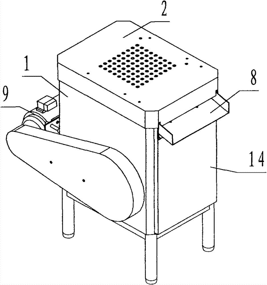
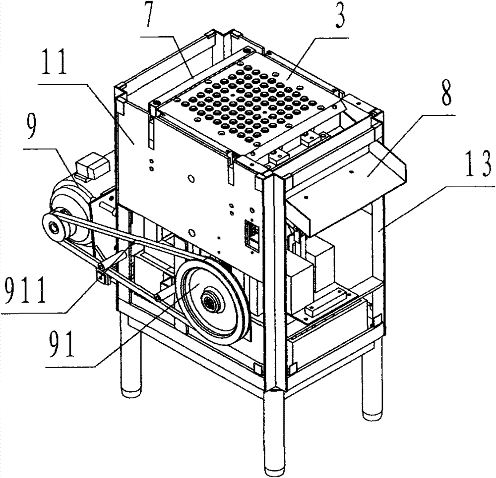
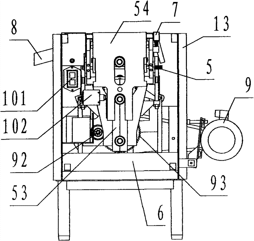
[0043] refer to Figure 1 to Figure 11 , a reciprocating one-time inverted capsule demoulding machine of the present invention, comprising a body 1, a lifting cover 2, a clamping plate 3, a tube jacking plate 4, a ejector rod plate 5, a bellows 6, a tuyere 7, an inclined bucket 8, Tube jacking reciprocating mechanism, ejector plate reciprocating mechanism, piston reciprocating mechanism, power transmission mechanism, and electrical control system, wherein: the body 1 includes wall panels 11, support plates 12, brackets 13, shells 14, and beam plates 15 , used to carry the steel frame body of each part of the capsule demoulding machine; the bracket 13 is a frame body made of angle steel to form the twelve edges and the bottom of the rectangular body 1; two wall panels 11 and two beam panels 15 The frame beam plate that surrounds a rectangle is fixed on the top of the support 13, the wall plate 11 is positioned at the two sides overlooking the long side of the body 1, the suppor...


PUM


Abstract

The invention discloses a once reciprocating reverse jacking type capsule de-molding machine which comprises a machine body (1), a lifting cover (2), a clamping and pulling plate (3), a pipe-jacking plate (4), a rod-jacking plate (5), an air box (6), an air port (7), an inclined sliding hopper (8), a pipe-jacking plate reciprocating mechanism, a rod-jacking plate reciprocating mechanism, a piston reciprocating mechanism, a power transmission mechanism and an electric control system. The technical scheme adopted by the invention is as follows: the clamping and pulling plate is fixed on the upper part of the machine body; the lifting cover capable of performing lifting motion is arranged above the clamping and pulling plate; the pipe-jacking plate capable of performing lifting motion is arranged below the clamping and pulling plate; the rod-jacking plate capable of performing lifting motion is arranged below the pipe-jacking plate; and the air box is arranged on the lower part of the machine body. According to the technical scheme, the problems and defects of the prior art that the size of the capsule de-molding machine is big and the reciprocating secondary de-molding efficiency is low are overcome. By means of the structure of finishing capsule de-molding through once reciprocating, the capsule de-molding machine is ensured to achieve the purpose of having compact and smart machine body, being efficient in de-molding, and being suitable for matching with a mass production line.

Description

technical field [0001] The invention relates to equipment for producing medicine capsules, in particular to a reciprocating one-time inverted capsule demoulding machine for releasing capsules from a mold during capsule production. Background technique [0002] The capsule demoulding machine of the prior art adopts a clamping plate for demoulding, and the clamping plate is provided with many clamping sleeves arranged in a matrix, and the whole process of capsule demoulding is completed through the action program of clamping, transposition, and ejection. Due to the technical process requirements that the clamping sleeve must reciprocate twice up and down and transposition, the demoulding machine body is larger and occupies more space, and the reciprocating secondary demoulding process makes the demoulding efficiency low, which is not conducive to the supporting application of large-scale production lines . Therefore, the capsule demoulding machine of the prior art has the pro...

Claims


Application Information

Patent Timeline
Patent Type & Authority Patents(China)
IPC IPC(8): A61J3/07
Inventor 徐家业
Owner 徐家业
Why Eureka
Try Eureka