
Operating speed control system and method for combine harvester

A combined harvester and speed control technology, which is applied to harvesters, agriculture, cutters, etc., can solve the problems of low sensitivity of mechanical induction sensors, limited adjustment accuracy, and poor ability to feel the change of feeding amount, so as to reduce machine hands. The effect of reducing the number of operations, reducing labor intensity and improving work efficiency

Inactive Publication Date: 2011-06-01
CHINA AGRI UNIV
View PDF2 Cites 25 Cited by
  • Summary
  • Abstract
  • Description
  • Claims
  • Application Information

AI Technical Summary

Problems solved by technology

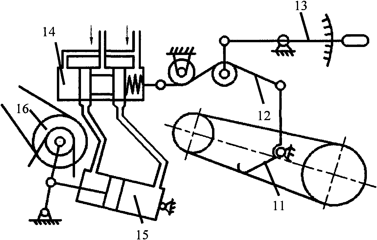
[0004] There are following deficiencies in the above-mentioned prior art: the landform environment in the field is complex, and the vibration and fluctuation of the harvesting operation are relatively large, such as figure 1 As shown, the sensitivity of the mechanical induction sensor should be low, resulting in poor ability to sense the change of feed amount
However, there are gaps in the control time of the electromagnetic hydraulic valve, and the adjustment accuracy is limited. Frequent start and stop may easily cause the solenoid valve to overheat; and the electromagnetic hydraulic valve has high requirements on the cleanliness of the oil medium, and inferior oil will seriously affect the reliability and service life of the system.
[0006] Combining the above two existing technologies, simply using the feed amount as a measure to control the operating speed cannot well reflect the influence of complex factors such as grain dryness and humidity, grass-to-grain ratio, and ground conditions, and the control accuracy is not high.

Method used


Image

  • Operating speed control system and method for combine harvester
  • Operating speed control system and method for combine harvester
  • Operating speed control system and method for combine harvester

Examples


Embodiment Construction

[0034] The specific implementation manners of the present invention will be further described in detail below in conjunction with the accompanying drawings and embodiments. The following examples are used to illustrate the present invention, but are not intended to limit the scope of the present invention.

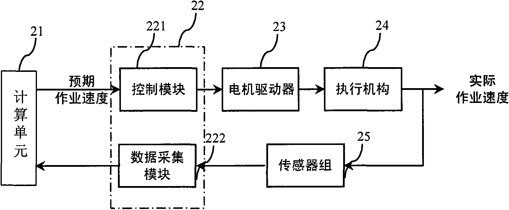
[0035] Such as figure 2 As shown, the combined harvester operating speed control system provided by the present invention includes a computing unit 21, which is used to process the received data and issue control instructions with the expected operating speed as the target; the measurement and control box 22 is used to collect sensor groups 25 The obtained data is transmitted to the calculation unit 21, and the control instruction of the calculation unit 21 is converted into a pulse control signal, and output to the motor driver 23; the motor driver 23 is used to receive the pulse control signal and control the actuator 24 according to the control Instruction work; the s...


PUM


Abstract

The invention discloses an operating speed control system and method for a combine harvester. The system comprises a computing unit, a measurement and control box, a motor driver and a sensor group, wherein, the computing unit processes the received data and sending out a control instruction which takes the expected operating speed as a target; the measurement and control box collects the data acquired by the sensor group, transfers the data to the computing unit, converts the control instruction of the computing unit into a pulse control signal and then outputs the signal to the motor driver; the motor driver receives the pulse control signal and controls an actuating mechanism to work according to the control instruction; and the sensor group acquires the torque and revolving speed of a threshing cylinder, the revolving speed and operating speed of an engine, and the stroke of a variable speed oil cylinder. By utilizing the system, the optimum operating speed of the combine harvester can be determined so as to automatically meet the requirements for harvest quality influence factors such as dry and wet degree, ratio of grain to straw, ground condition, feed quantity of different grains and the like.

Description

technical field [0001] The invention relates to the field of agricultural machinery, in particular to an intelligent control system for the operating speed of a combine harvester. Background technique [0002] Combine harvesters can reduce grain loss, reduce work intensity, and improve work efficiency. At present, the degree of mechanized harvesting of major domestic food crops, such as corn, rice, and wheat, has reached 80%. The quality of crop grain harvest is closely related to the working status, operation level, crop attributes and field landform of the combine harvester itself. High operating speed can improve production efficiency, but if the operating speed is too fast, it will overload the threshing drum, even cause blockage, increase the threshing loss rate of crops, and increase the total loss. In order to control the total loss of the harvest within the allowable range, the operator needs to pay close attention to the working status of the machine during the ope...

Claims


Application Information

Patent Timeline
IPC IPC(8): A01D41/127
Inventor 王书茂康峰罗瑞龙
Owner CHINA AGRI UNIV
Learn More