
Switching switch device

A technology of switching and automatic switching, which is applied in the output power conversion device, circuit device, and AC power input is converted into AC power output, etc. Simple structure, low cost and short action time

Active Publication Date: 2013-06-12
XI AN MENGCHUANG ELECTRICAL APPLIANCE
View PDF0 Cites 0 Cited by
  • Summary
  • Abstract
  • Description
  • Claims
  • Application Information

AI Technical Summary

Problems solved by technology

However, the existing problems are: the voltage regulating device is driven by the servo motor, and it cannot be shifted, but must be switched step by step; the switching transition time is long due to the inherent mechanical time; it needs to be packaged in transformer oil as a whole; the accident rate is high during frequent operation; the price expensive

Method used


Image

  • Switching switch device
  • Switching switch device

Examples


Embodiment Construction

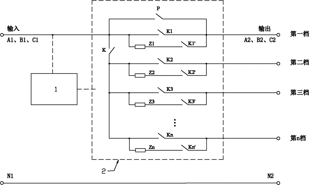
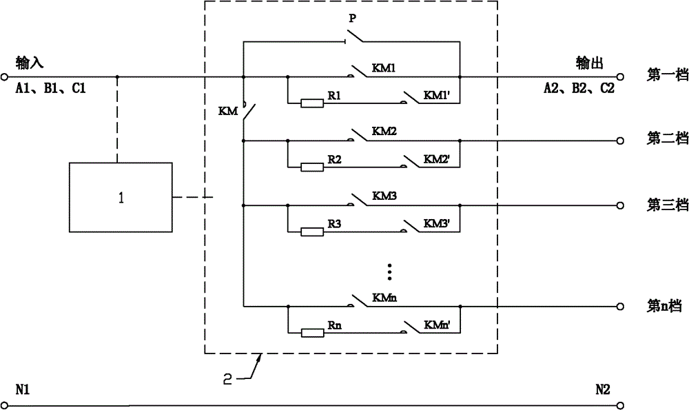
[0022] see figure 1 , The automatic changeover switch of the present invention is made up of automatic control device 1, changeover switch device 2. The changeover switch device 2 includes a multi-pole switch, an anti-welding switch K and a bypass switch P. A multi-pole switch consists of multiple single-pole switches. The unipolar switch includes a main switch K1, an auxiliary switch K1' and a transition impedance unit Z1, the auxiliary switch K1' is connected in series with the transition impedance unit Z1, and the series circuit of the auxiliary switch K1' and the transition impedance unit Z1 is connected in parallel with the main switch K1. Single-stage switches can be multiple, such as figure 1 As shown, the main switch units can be K1, K2, ... Kn, the auxiliary switch units can be K1', K2', ... Kn, and the transition impedance units can be Z1, Z2, ... Zn.

[0023] The main switch, auxiliary switch, anti-welding switch, and bypass switch are contactors, thyristors, cir...


PUM


Abstract

The invention provides a switching switch device, which comprises an automatic switching switch, wherein the automatic switching switch is a multi-pole switch formed by connecting two or more than two single-pole switches in parallel. The switching switch device is the multi-pole switch which can perform trip switching automatically and arbitrarily and can switch circuits quickly and effectively.

Description

technical field [0001] The invention relates to a switch, in particular to a switch capable of automatic switching. Background technique [0002] With the rapid development of the national economy and urban and rural construction, in the power system, the requirements for the continuity, stability and reliability of its power supply are getting higher and higher. However, due to the fluctuation of power supply voltage and the change of load size, the power supply voltage of the system is constantly changing, which will affect the normal operation of electrical equipment in severe cases. In addition, in some special industries, the working voltage of the equipment is required to be automatically controlled and adjusted according to the requirements, so as to ensure the production quality, production efficiency and equipment safety. For this reason, how to quickly and effectively increase or decrease the voltage according to the requirements, and realize the switching without...

Claims


Application Information

Patent Timeline
Patent Type & Authority Patents(China)
IPC IPC(8): H02P13/06H02M5/12H01F29/04H02J9/06
Inventor 弋东方弋戈赵红玉王志
Owner XI AN MENGCHUANG ELECTRICAL APPLIANCE
Learn More