
Power supply circuit and liquid crystal display device using the same

A power supply circuit and circuit technology, applied in the direction of output power conversion devices, electrical components, and electrical variables, can solve the problem of high cost of power supply circuits, and achieve the effects of improving power supply flexibility, low cost, and reducing quantity

Inactive Publication Date: 2011-12-21
INNOCOM TECH (SHENZHEN) CO LTD +1
View PDF0 Cites 0 Cited by
  • Summary
  • Abstract
  • Description
  • Claims
  • Application Information

AI Technical Summary

Problems solved by technology

[0009] In order to solve the problem of high cost of power supply circuits in the prior art, it is necessary to provide a low-cost power supply circuit

Method used


Image

  • Power supply circuit and liquid crystal display device using the same
  • Power supply circuit and liquid crystal display device using the same
  • Power supply circuit and liquid crystal display device using the same

Examples


Embodiment Construction

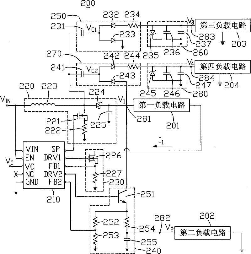
[0019] see figure 2 , which is a circuit diagram of the first embodiment of the power supply circuit of the present invention. The power supply circuit 200 can be applied to a liquid crystal display device (not shown), which includes a pulse width modulation circuit 210, a switching regulator circuit 220, a first control circuit 230, a second control circuit 240, a first A voltage transforming circuit 250 , a first voltage stabilizing circuit 260 , a second voltage transforming circuit 270 and a second voltage stabilizing circuit 290 .

[0020] The pulse width modulation circuit 210 includes a power input terminal VIN, an enable terminal EN, a signal input terminal VC, a reserved terminal NC, a ground terminal GND, a pulse signal output terminal SP, and a first control terminal DRV1 , a first feedback terminal FB1, a second control terminal DRV2 and a second feedback terminal FB2. Wherein the power input terminal VIN is used to receive the working power V of the pulse width...


PUM


Abstract

The invention provides a power supply circuit. The power supply circuit includes a pulse width modulation circuit, a switch voltage regulator circuit, a first control circuit and a second control circuit. The pulse width modulation circuit outputs a pulse signal, a first control signal and a second control signal respectively. The switching regulator circuit receives the pulse signal and generates a first DC voltage, the first control circuit receives the first control signal, and controls whether the first DC voltage is applied to a first load under the action of the first control signal The circuit is powered. The second control circuit converts the first DC voltage into a second DC voltage, receives the second control signal, and controls whether the second DC voltage supplies power to a second load circuit under the action of the second control signal . The invention also provides a liquid crystal display device using the power supply circuit.

Description

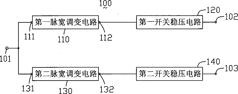
technical field [0001] The invention relates to a power supply circuit and a liquid crystal display device using the power supply circuit. Background technique [0002] A power supply circuit is usually arranged inside the liquid crystal display device. When the liquid crystal display device is working, the power supply circuit provides working power for the liquid crystal panel and the backlight module inside the liquid crystal display device. [0003] see figure 1 , is a circuit block diagram of a prior art power supply circuit applied to a liquid crystal display device. The power supply circuit 100 includes an input terminal 101, a first pulse width modulation (Pulse Width Modulation, PWM) circuit 110, a first switch regulator circuit 120, a second pulse width modulation circuit 130, a second switch A voltage stabilizing circuit 140 , a first output terminal 102 and a second output terminal 103 . [0004] The first pulse width modulation circuit 110 includes an input ...

Claims


Application Information

Patent Timeline
Patent Type & Authority Patents(China)
IPC IPC(8): G02F1/133H02M3/155H02M3/156G09G3/36
Inventor 李仲儒陈汉昌
Owner INNOCOM TECH (SHENZHEN) CO LTD
Learn More