Electric connector and electric coupler assembly

A technology of electrical connectors and electrical joints, which is applied in the direction of connection and connection device parts, circuits, etc., can solve the problems of complex structure of lever-type locking parts, and achieve the effect of simple structure, firm fixation and quick removal

Inactive Publication Date: 2011-05-25
MITAC PRECISION TECH CO LTD SHUNDE DISTRICT FOSHAN CITY
View PDF2 Cites 2 Cited by
  • Summary
  • Abstract
  • Description
  • Claims
  • Application Information

AI Technical Summary

Problems solved by technology

However, the structure of the lever-type catch in the above two cases is relatively complicated, and r

Method used


Image

  • Electric connector and electric coupler assembly
  • Electric connector and electric coupler assembly
  • Electric connector and electric coupler assembly

Examples


Embodiment Construction

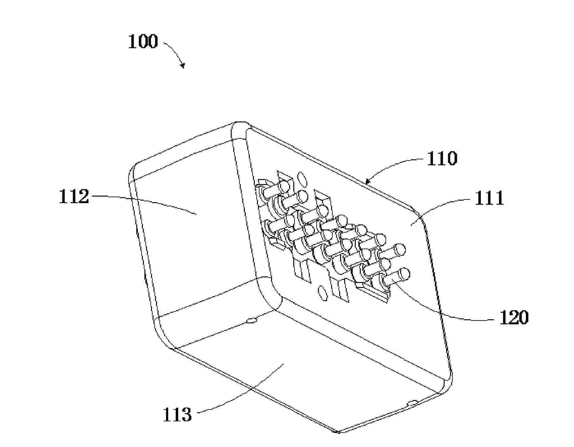
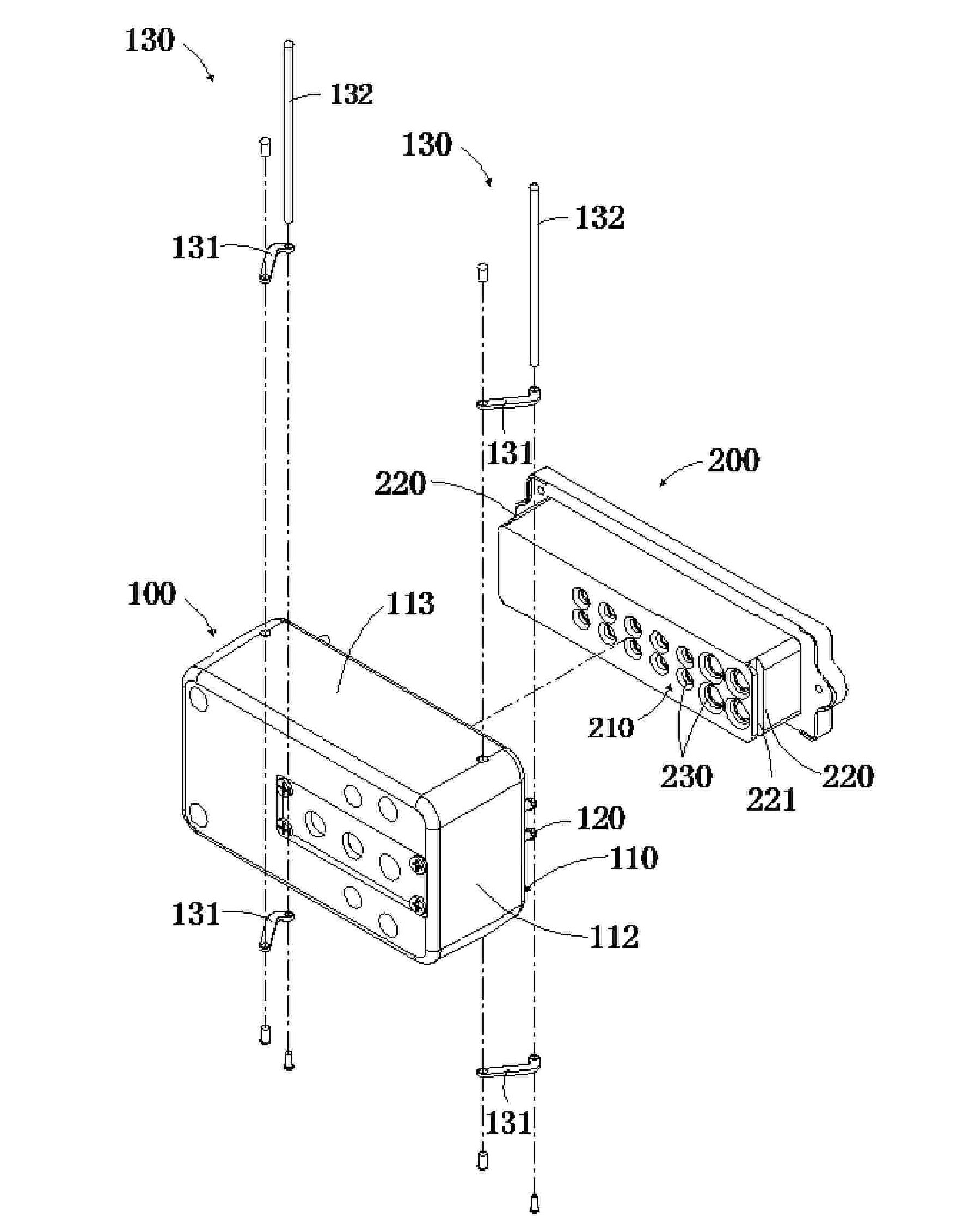
[0022] refer to figure 1 , figure 2 ,and image 3 As shown, the electrical connector 100 proposed by the specific embodiment of the present invention includes a body 110 , a plurality of conductive pillars 120 , and two engaging members 130 .

[0023] refer to figure 1 , figure 2 and image 3 As shown, the body 110 has a connection surface 111, two opposite side surfaces 112, and two opposite installation surfaces 113, the connection surface 111 is used to be combined with the electrical connector 200, and the connection surface 111 has at least two pairs and On the opposite sides, the two lateral surfaces 112 are located on the two opposite sides of the connection surface 111, and the installation surface 113 is located on the other two opposite sides of the connection surface 111. In addition, the end of a cable (not shown) is connected to the body 110, for feeding or receiving electric signals.

[0024] refer to figure 1 as shown, figure 1 The locking part 130 is ...


PUM


Abstract

The invention provides an electric connector which is used for connecting to an electric coupler so as to form an electric coupler assembly, wherein the electric connector comprises a main body, a plurality of conductive columns and two clipping elements; the main body comprises a connection surface; the conductive columns are vertically arranged on the connection surface and used for contacting with the electrode of the electric coupler; the conductive columns can be shortened by pressing; the conductive columns are protruded from the height of the connection surface while generating an elastic force for pushing outwards so as to push the electric connector far from the electric coupler; the clipping elements are respectively equipped with a rotation arm and a clipping rod; the rotation arms are pivoted on the main body; and the clipping rods are vertically connected to the rotation arms and are used for buttoned on the electric coupler. The electric connector and the electric coupler assembly provided by the invention have the advantages that the clipping elements firmly buttoned on the electric coupler by pushing the electric connector far from the electric coupler via the conductive columns, and electric connector is prevented from dropping off from the electric coupler.

Description

【Technical field】 [0001] The invention designs an electric connector and an electrical connector assembly, in particular relates to an electrical connector assembly capable of firmly fixing the electrical connector to the electrical connector. 【Background technique】 [0002] It is related to electrically connecting two circuit systems to each other, such as connecting a portable computer and an expansion base, through matching electrical connectors and electrical connectors. In order to prevent the electrical connectors from falling off from the electrical connectors, the electrical connectors and electrical connectors An additional fixing piece is usually added between them to ensure that the electrical connector is securely fixed to the electrical connector. A common practice is to use a thumb screw to pass through the electrical connector. After the electrical connector is connected to the electrical connector, the user further turns the thumb screw to lock the front end ...

Claims


Application Information

Patent Timeline
IPC IPC(8): H01R13/629H01R13/639
Inventor 萧秀敏
Owner MITAC PRECISION TECH CO LTD SHUNDE DISTRICT FOSHAN CITY
Why Eureka
Try Eureka