High-precision wide-range low-coherent interference shift demodulation device and demodulation method thereof
A low-coherence interference, large-range technology, applied in the field of displacement information demodulation, can solve the problems of limited pixels of linear array CCD, small measurement range, measurement accuracy only in the order of microns, etc., achieving high reliability and wide application range. Effect
- Summary
- Abstract
- Description
- Claims
- Application Information
AI Technical Summary
Problems solved by technology
Method used
Image
Examples
Embodiment 1
[0037] Embodiment 1: A high-precision, large-range and low-coherence interference displacement demodulation device
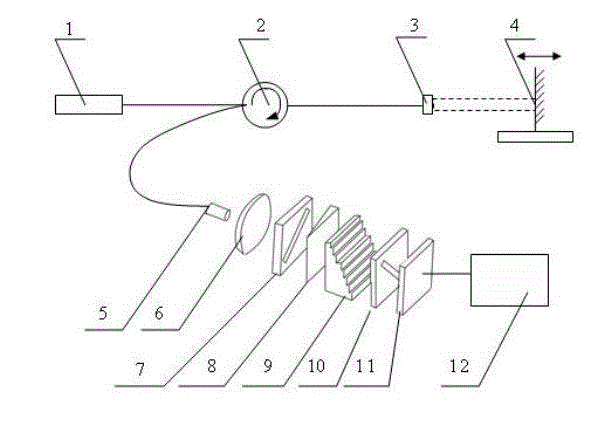
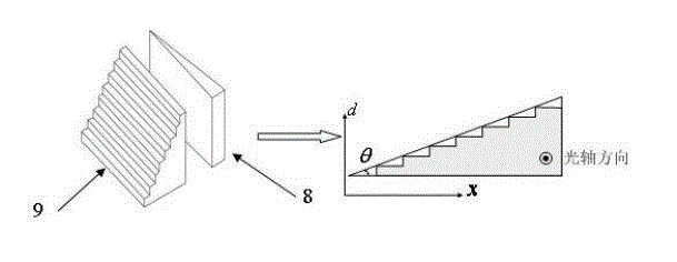
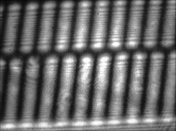
[0038] Such as figure 1 As shown, the light emitted by the broadband light source 1 passes through the optical circulator 2 and reaches the self-focusing collimating lens 3 on the sensor side, part of the light is reflected by the end reflective surface of the self-focusing collimating lens 3, and the other part of the light is self-focusing and collimating The lens 3 is collimated and emitted to the fixed mirror 4 fixed on the object to be detected, and after being reflected, this part of the light is coupled into the optical fiber again. The reflected two beams of light are transmitted to the beam expander lens 6 through the optical circulator 2 and the optical fiber connector 5 , and the optical fiber connector 5 is located on the focal length of the beam expander lens 6 to realize beam expansion and penetrate the effective photosensitive area of the area ...
Embodiment 2
[0039] Embodiment 2: A high-precision, large-range and low-coherence interference displacement demodulation method
[0040] The demodulation process of the above-mentioned low-coherence interference displacement demodulation device is as follows:
[0041] figure 1 The light from the broadband light source 1 in the sensor passes through the optical circulator 2 and reaches the self-focusing collimating lens 3 on the sensing side, part of the light is reflected by the end face reflection surface of the self-focusing collimating lens 3, and the other part of the light is reflected by the self-focusing collimating lens 3 The collimated light is emitted to the fixed mirror 4 of the object to be detected, and after being reflected, this part of the light is coupled into the optical fiber again, and the two parts of the light have an optical path difference related to the displacement of the object to be detected , It is twice the distance between the self-focusing collimating...
Embodiment 3
[0051] Embodiment 3: application example
[0052] If the self-focusing collimating lens 3 and the fixed mirror 4 are used as the two reflection surfaces of the fiber optic Fab, the demodulation device and demodulation method can be used for the absolute cavity length demodulation of the fiber Fab. Taking the fiber-optic F-Per pressure sensor as an example, the fixed reflector 4 is fixed on the pressure diaphragm. When the F-P cavity length is small enough, the self-focusing collimating lens 3 can be omitted, and the optical fiber can be directly used instead, that is, the fixed reflector The mirror 4 and the end face of the fiber form a Fab cavity. When the external pressure acts on the diaphragm, the diaphragm deforms, driving the mirror 4 to move axially, and the demodulation device can match the current F-P cavity length through optical path difference scanning, thereby sensing the deformation of the diaphragm, and then according to The formula or calibration factor calc...
PUM
 Abstract
Description
Claims
Application Information
 - Generate Ideas
- Intellectual Property
- Life Sciences
- Materials
- Tech Scout
- Unparalleled Data Quality
- Higher Quality Content
- 60% Fewer Hallucinations
Browse by: Latest US Patents, China's latest patents, Technical Efficacy Thesaurus, Application Domain, Technology Topic, Popular Technical Reports.
© 2025 PatSnap. All rights reserved.Legal|Privacy policy|Modern Slavery Act Transparency Statement|Sitemap|About US| Contact US: help@patsnap.com


