
Double-frequency printing type yagi antenna

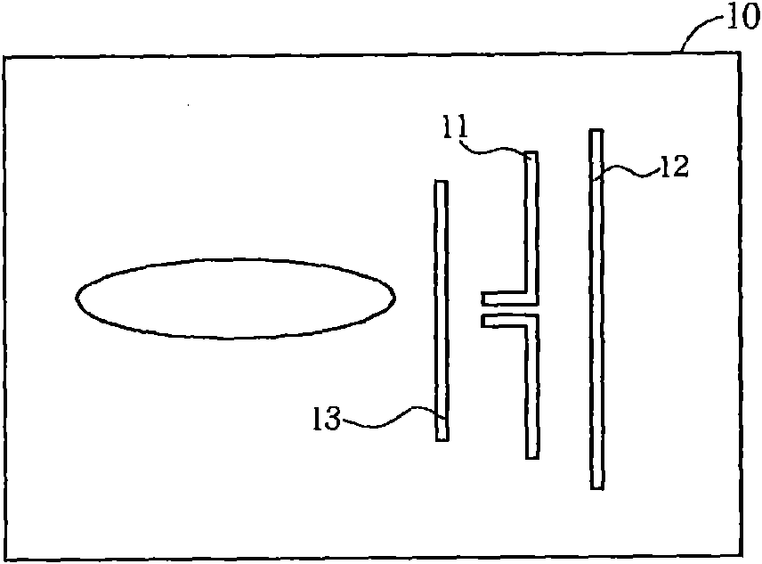
A technology of Yagi antenna and dipole antenna, which is applied in the field of dual-frequency printed Yagi antenna, and can solve the problems that cannot meet the requirements of multi-band

Active Publication Date: 2011-05-04
MEDIATEK INC
View PDF6 Cites 42 Cited by
  • Summary
  • Abstract
  • Description
  • Claims
  • Application Information

AI Technical Summary

Problems solved by technology

[0005] However, the traditional printed Yagi antenna is a single-frequency antenna, which cannot meet the multi-band requirements of current wireless communication products, so there is a need for improvement

Method used


Image

  • Double-frequency printing type yagi antenna
  • Double-frequency printing type yagi antenna
  • Double-frequency printing type yagi antenna

Examples


Embodiment Construction

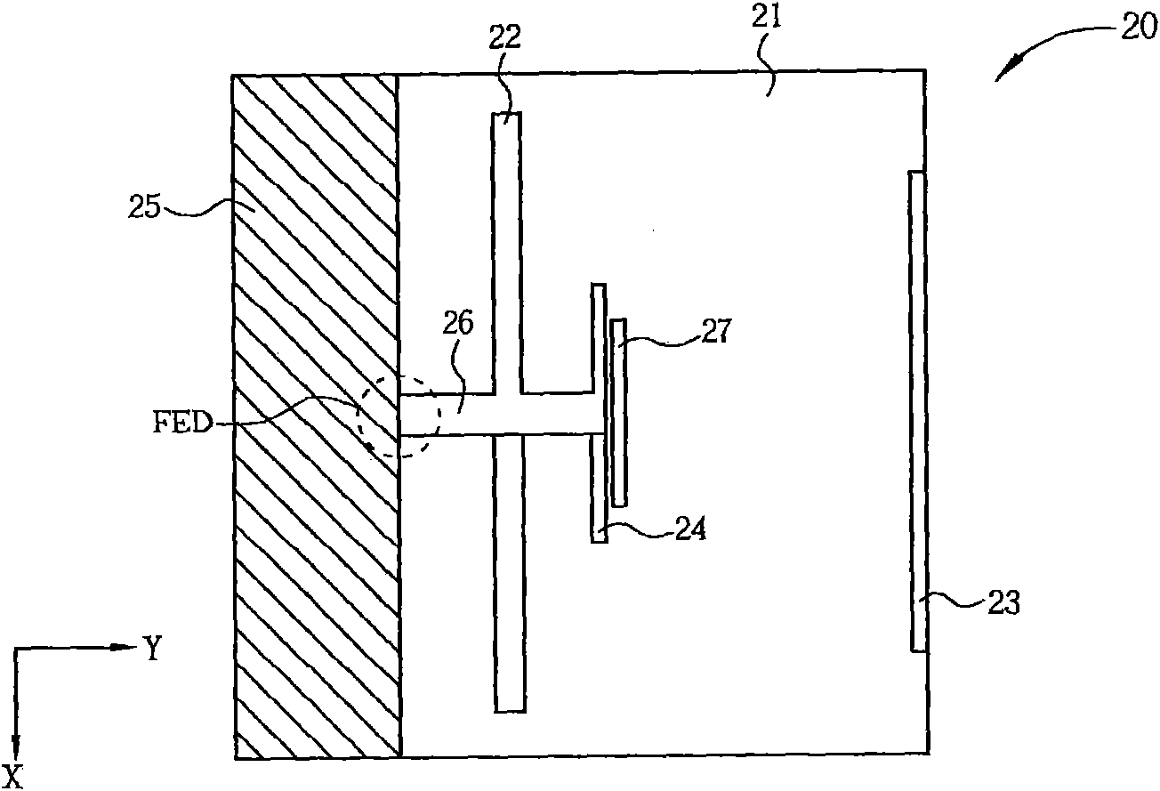
[0033] Please refer to figure 2 , figure 2 It is a schematic diagram of an embodiment of a dual-frequency printed Yagi antenna 20 of the present invention. The dual frequency printed Yagi antenna 20 includes a substrate 21 , a low frequency driver 22 , a low frequency director 23 , a high frequency driver 24 , a reflector 25 and a transmission line 26 . The low frequency driver 22 is formed on the substrate 21 for generating a low frequency radiation pattern. The low-frequency director 23 is formed on one side of the low-frequency driver 22 on the substrate 21, and is used to guide the low-frequency radiation pattern to radiate in the +Y-axis direction. The high-frequency driver 24 is formed between the low-frequency driver 22 and the low-frequency director 23 on the substrate 21 to generate a high-frequency radiation pattern. For the high-frequency signal generated by the high-frequency driver 24, a distance between the high-frequency driver 24 and the low-frequency dire...


PUM


Abstract

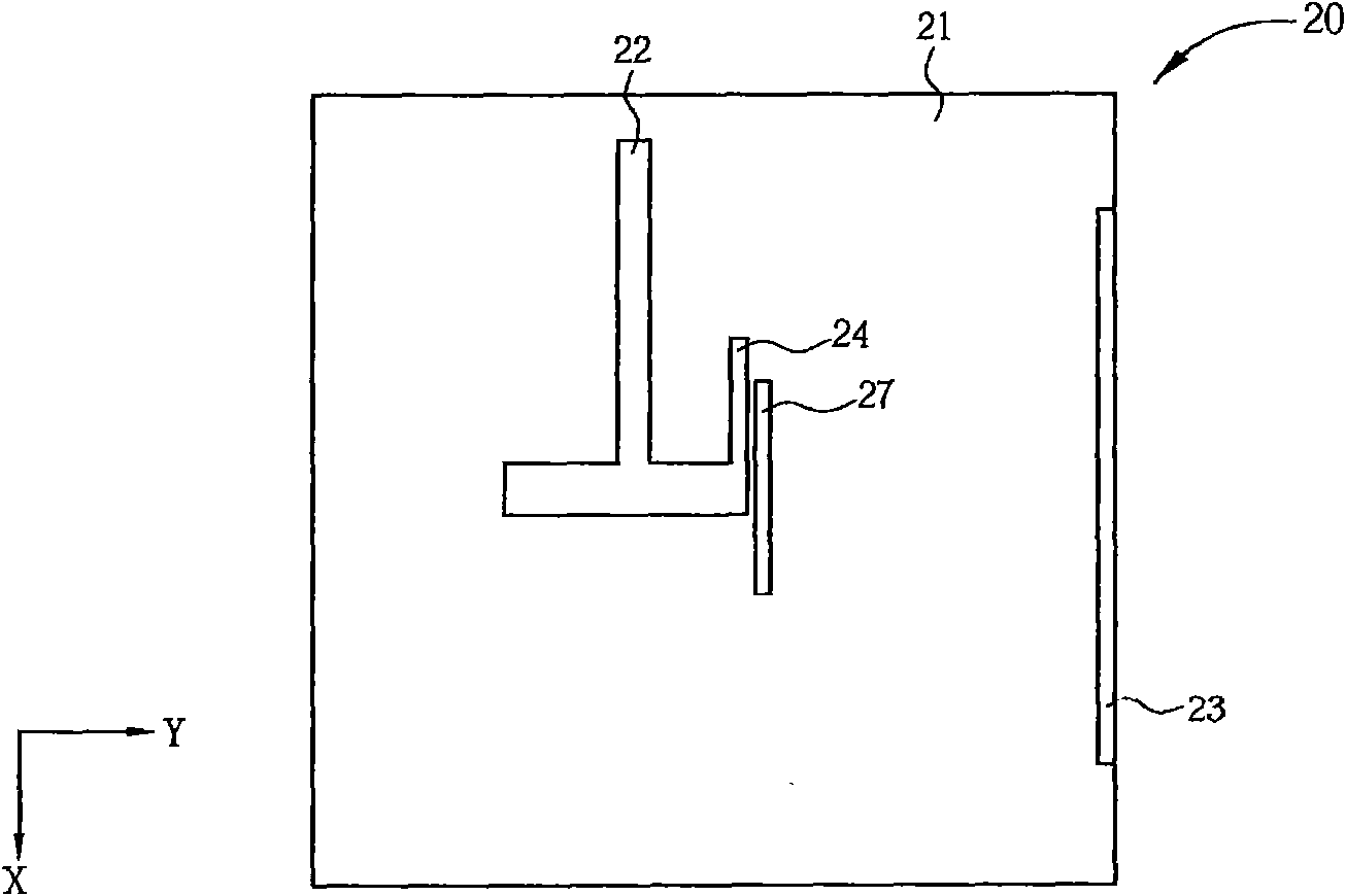
The invention discloses a double-frequency printing type yagi antenna which comprises a substrate, a first driver, a first director, a second driver and a reverberator. The first driver is formed on the substrate, and is used for generating a radiation field type of a first waveband. The first director is formed at one side of the first driver on the substrate, and is used for guiding the radiation field type of the first waveband to the first direction. The second driver is formed between the first driver and the first director on the substrate, and is used for generating the radiation field type of the second waveband. The reverberator is formed at one side of the first driver on the substrate, and is used for reverberating the first waveband and the second waveband at the radiation field type to the first direction.

Description

technical field [0001] The invention relates to a dual-frequency printed Yagi antenna, in particular to a dual-frequency printed Yagi antenna with high directivity radiation field. Background technique [0002] In the modern information society, various wireless communication networks have become one of the most important ways for the public to exchange voice or text information, data, data, and audio-visual files. Access to these wireless communication networks that carry information through wireless electromagnetic waves requires the use of antennas. Therefore, the research and development of antennas has become one of the focuses of modern information industry manufacturers. In order to realize a wireless communication device that is smaller in size and convenient for users to carry around, such as mobile phones, personal digital assistants (PDAs), and wireless USB transmitters (Wireless USB Dongle), the volume of the antenna should also be reduced as much as possible to ...

Claims


Application Information

Patent Timeline
Patent Type & Authority Applications(China)
IPC IPC(8): H01Q19/30H01Q5/00H01Q13/08H01Q5/49
Inventor 陈信錩吴民仲
Owner MEDIATEK INC
Learn More