MEMS pressure sensor

一种压力传感器、压力的技术,应用在测量流体压力、压电器件/电致伸缩器件、通过电磁元件测量流体压力等方向,能够解决机械谐振器的运动电阻时间不十分稳定、测量谐振器不可靠等问题

Active Publication Date: 2011-04-27
XIAO TESTING CO LTD
View PDF4 Cites 25 Cited by
  • Summary
  • Abstract
  • Description
  • Claims
  • Application Information

AI Technical Summary

Problems solved by technology

However, the motional resistance of mechanical resonators is not very stable over time, making these resonators unreliable for measuring absolute pressure over time, especially low pressures

Method used


Image

  • MEMS pressure sensor
  • MEMS pressure sensor
  • MEMS pressure sensor

Examples


Embodiment Construction

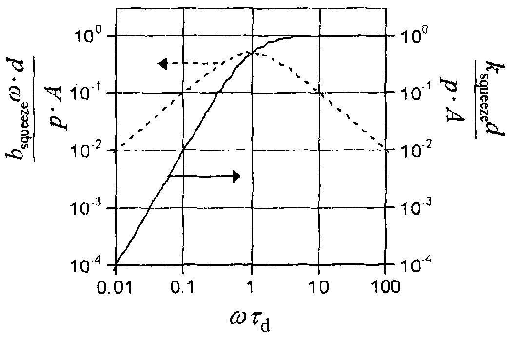
[0057] As noted above, it will be appreciated that monitoring the magnitude or dissipation of the resonator signal may be used to indicate pressure. The invention is based on a different monitoring mechanism which influences the resonance frequency. If the thin film of gas within the resonator structure cannot escape quickly enough, this will contribute to the spring constant k.

[0058] It can be assumed that for pressures in the range of 0.1 kPa, ie, within the Knudsen gas regime, regardless of viscosity, the mean free path of gas molecules is larger than the device size (ie >100 μm).

[0059] In the equation of motion (1), the damping coefficient b and the spring constant k can be decomposed into a contribution from the (silicon) structure b mat and the contribution due to gas damping b gas .

[0060] b=b mat +b gas (6)

[0061] k=k mat +k gas (7)

[0062] Damping coefficient b gas and elastic coefficient k gas is given by:

[0063] b ...


PUM

PropertyMeasurementUnit
widthaaaaaaaaaa
areaaaaaaaaaaa
lengthaaaaaaaaaa

Abstract

A MEMS pressure sensor for sensing the pressure in a sealed cavity of a MEMS device, comprises a resonant MEMS device having a pressure sensor resonator element which comprises an array of openings. The resonant frequency of the resonant MEMS device is a function of the pressure in the cavity, with resonant frequency increasing with pressure. Over the pressure range 0 to 0.1 KPa, the average change in frequency is at least 10-6 / Pa. The invention is based on the recognition that for fast oscillation, the elastic force causes the resonance frequency to shift. Therefore, it is possible to sense the pressure by a device with resonance frequency that is sensitive to the pressure.

Description

technical field [0001] The present invention relates to MEMS pressure sensors, and in particular to sensing pressure within a cavity of a resonant MEMS device. Background technique [0002] During the MEMS fabrication process, microstructures are usually encapsulated in hermetically sealed microcavities to maintain vacuum conditions for proper operation of MEMS devices. The microcavity has a very small volume (typically 200×200×2 μm 3 ), air leakage or deflation can easily break the vacuum. Therefore, it is important to have a means of monitoring the pressure in the microcavity during product launch, during qualification of a product process, or even during operation of a resonant MEMS device. [0003] figure 1 The pressure dependence of the oscillation amplitude ( S12 ) of a bulk mode timing resonator at a frequency of 25.8 MHz is shown. For pressures above 10mbar (1kPa), the resonance amplitude starts to degrade. [0004] from figure 1 As can be seen in , high freque...

Claims


Application Information

Patent Timeline
Patent Type & Authority Applications(China)
IPC IPC(8): G01L9/00B81B3/00
CPCG01L9/0019G01L21/22
Inventor 马菲积斯·斯维伦扬·雅各布·科宁赫尔曼·西恩拉德·威廉·贝吉林克
Owner XIAO TESTING CO LTD
Why Eureka
Try Eureka