Method for measuring groove center distance of outer groove of bearing

A measurement method, the technology of groove center distance, applied in the direction of mechanical clearance measurement, etc., can solve the problems of increasing production costs of enterprises, expensive detectors, actual groove center distance errors, etc., to improve measurement accuracy, reduce production costs, and improve production efficiency Effect

Inactive Publication Date: 2011-04-27
浙江斯菱汽车轴承股份有限公司
View PDF2 Cites 6 Cited by
  • Summary
  • Abstract
  • Description
  • Claims
  • Application Information

AI Technical Summary

Problems solved by technology

[0002] In recent years, my country's bearing industry has developed rapidly, but the domestic measurement technology for bearings is still relatively backward, especially the measurement method for the center distance of the outer groove of the bearing, and the center distance of the outer groove of the bearing is one of the important testing items of the bearing. It can directly affect the clearance value of the finished bearing; at present, the measurement of the center distance of the outer groove of the bearing in China generally uses the inspector to measure the actual groove center distance with a profiler; however, due to different inspectors, the measurement method is also different. However, the final measured actual groove center distance also has a large error, which will cause the actual groove center distance of the produced bearings to fail to meet the standard, seriously affect the clearance value of the finished bearing, and greatly reduce the bearing performance of the finished bearing. The pass rate also affects the production efficiency of the enterprise; and the detector is quite expensive, which also increases the production cost of the enterprise to a certain extent

Method used


Image

  • Method for measuring groove center distance of outer groove of bearing
  • Method for measuring groove center distance of outer groove of bearing

Examples


Embodiment Construction

[0015] The present invention will be described in further detail below in conjunction with the accompanying drawings and embodiments.

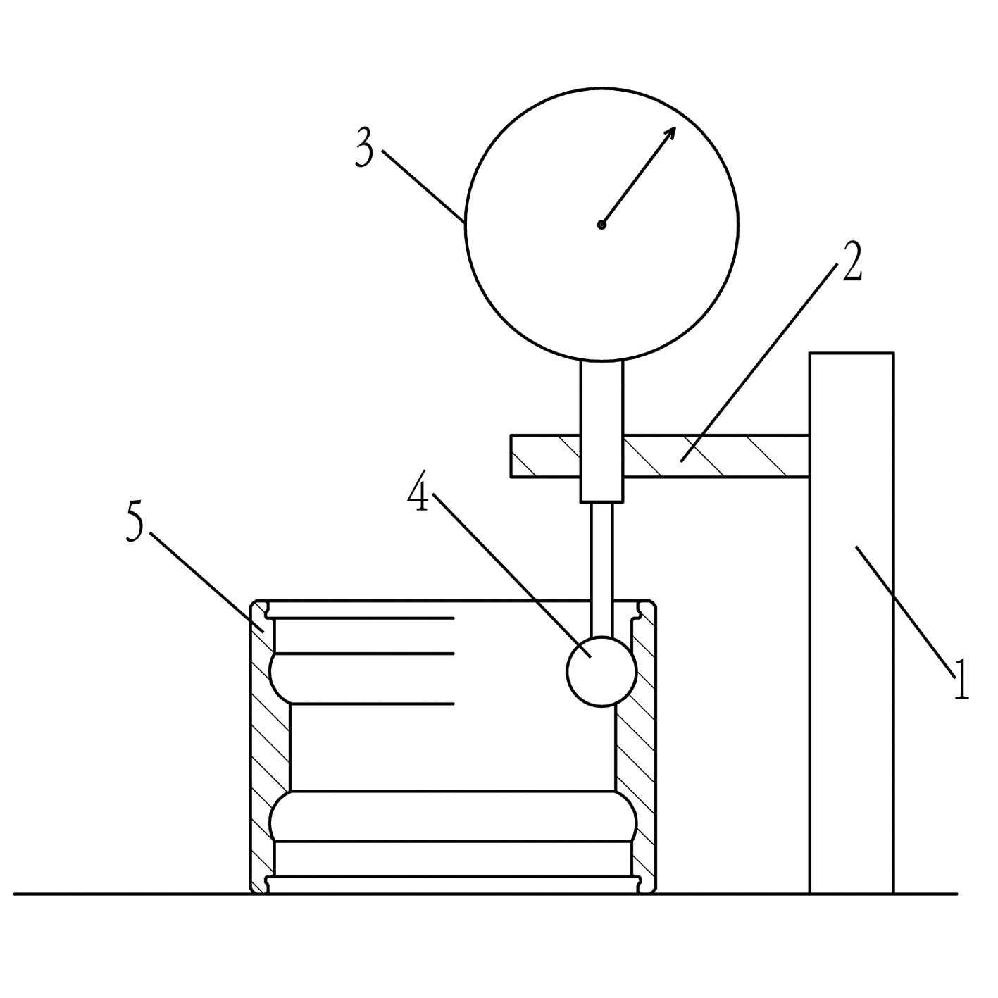
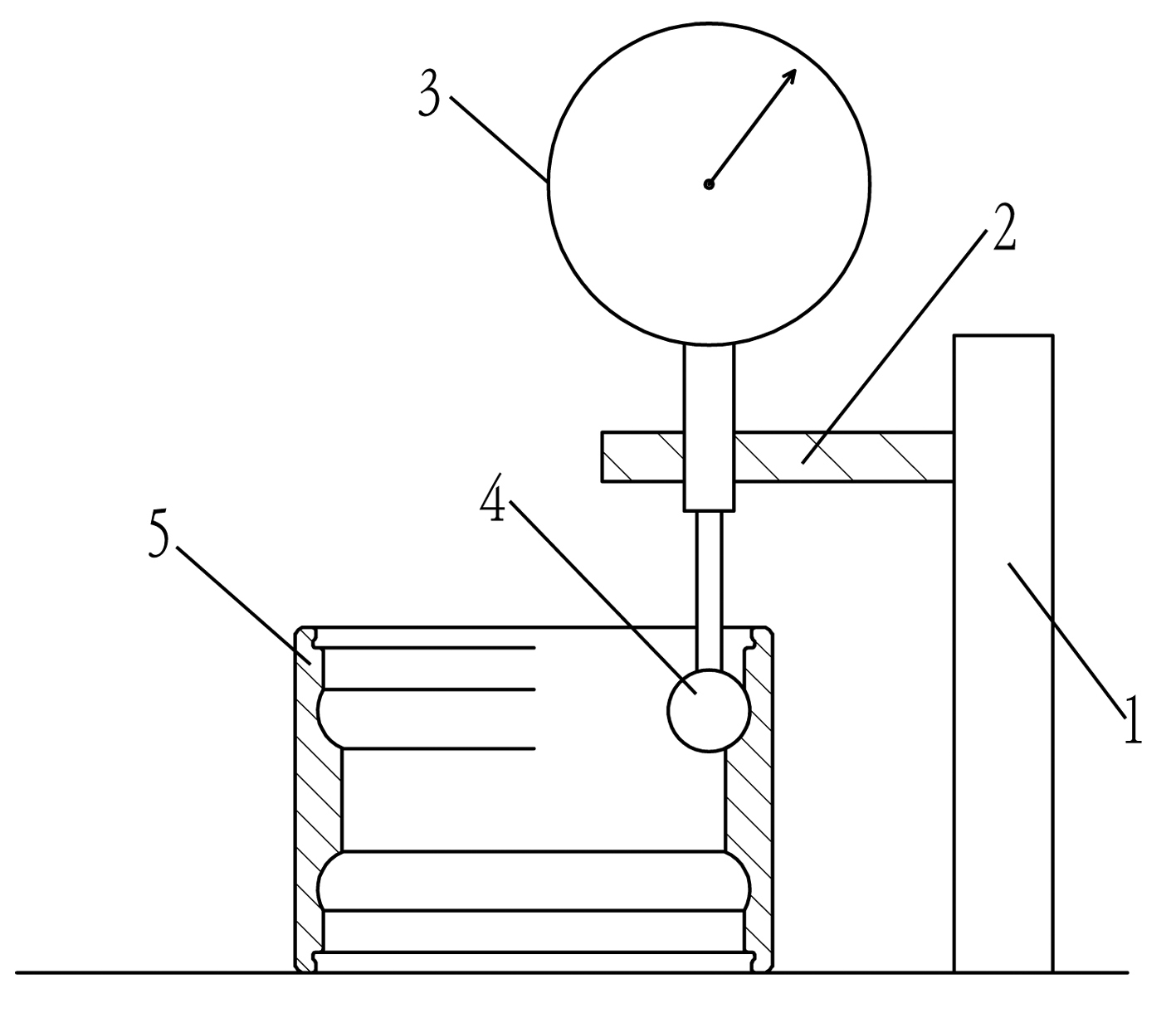
[0016] See attached picture. The measuring device of the present embodiment includes a base as a measuring plane, on which a column 1 is vertically fixed, and the column 1 is provided with a connecting rod 2 parallel to the base, and the connecting rod 2 is provided with a thousand A submeter 3; the measuring end of the micrometer 3 is a measuring ball 4, and the diameter d of the measuring ball 4 is the same as the measured channel radius R.

[0017] Utilizing the above-mentioned measuring device, when measuring in this embodiment, firstly, according to the theoretical value B of the bearing groove center distance 0 and the theoretical value A of the groove-top distance 0 , adjust the distance E=(A 0 +B 0 )-d / 2; then take the tested bearing 5 and place it on the measurement plane, so that the arc of its channel is completely consistent wi...


PUM


Abstract

The invention discloses a method for measuring the groove center distance of an outer groove of a bearing, which comprises the following steps of: a, preparing a micrometer and setting the measuring end of the micrometer as a measuring ball, wherein the diameter d of the measuring ball is equal to the radius R of a measured channel; b, adjusting a distance E between the lower end of the measuring ball of the micrometer and a measuring plane according to a theoretical value B0 of the groove center distance and a theoretical value A0 of a groove apex distance, wherein E=(A0+B0)-d / 2; c, putting the measured bearing on the measuring plane to ensure that one channel arc of the bearing is completely matched with the measuring ball of the micrometer, and measuring the reading X of the micrometer; d, turning the measured bearing to ensure that the other channel arc of the bearing is completely matched with the measuring ball of the micrometer, and measuring the reading Y of the micrometer; e, measuring the actual total height H of the measured bearing; and f, calculating the actual groove center distance B of the measured bearing according to a formula B=(X+Y)-H. The invention has the characteristics of simple detection method and high detection accuracy.

Description

technical field [0001] The invention belongs to the technical field of bearing measurement, in particular to a method for measuring the center distance of outer grooves of bearings. Background technique [0002] In recent years, my country's bearing industry has developed rapidly, but the domestic measurement technology for bearings is still relatively backward, especially the measurement method for the center distance of the outer groove of the bearing, and the center distance of the outer groove of the bearing is one of the important testing items of the bearing. It can directly affect the clearance value of the finished bearing; at present, the measurement of the center distance of the outer groove of the bearing in China generally uses the inspector to measure the actual groove center distance with a profiler; however, due to different inspectors, the measurement method is also different. However, the final measured actual groove center distance also has a large error, wh...

Claims


Application Information

Patent Timeline
Patent Type & Authority Applications(China)
IPC IPC(8): G01B5/14
Inventor 姜岭
Owner 浙江斯菱汽车轴承股份有限公司
Why Eureka
Try Eureka