
Standardized current conversion device of electric vehicle and distributed power source

A technology of distributed power supply and electric vehicle, applied in electric vehicle charging technology, electric vehicle, battery circuit device, etc., can solve the problems of high degree of uncertainty, output power fluctuation, harmonic pollution, etc., and reduce the total installed capacity of the system. , the effect of increasing the load rate

Inactive Publication Date: 2011-04-27
ELECTRIC POWER RES INST OF STATE GRID ZHEJIANG ELECTRIC POWER COMAPNY +1
View PDF4 Cites 27 Cited by
  • Summary
  • Abstract
  • Description
  • Claims
  • Application Information

AI Technical Summary

Problems solved by technology

[0004] (1) Operation control: The scheduling and operation of distributed power sources are controlled by the property owners of the power sources, which cannot be effectively regulated
[0005] (2) Output power fluctuations: The active input of distributed power sources using wind energy and solar energy has natural volatility, so the output power of distributed power sources fluctuates greatly, and the degree of uncertainty is high, which is likely to cause flicker due to grid voltage fluctuations
[0006] (3) Harmonic pollution: Distributed power sources often use rectification and inverter devices to connect to the power grid, which will output a large number of multiple harmonic currents to the power grid
[0009] (1) Loads sensitive to power quality: such as semiconductor production plants, paper mills, etc., if the voltage drops for tens of milliseconds, the production equipment will not work normally and a large amount of waste products will appear

Method used


Image

  • Standardized current conversion device of electric vehicle and distributed power source
  • Standardized current conversion device of electric vehicle and distributed power source
  • Standardized current conversion device of electric vehicle and distributed power source

Examples


Embodiment Construction

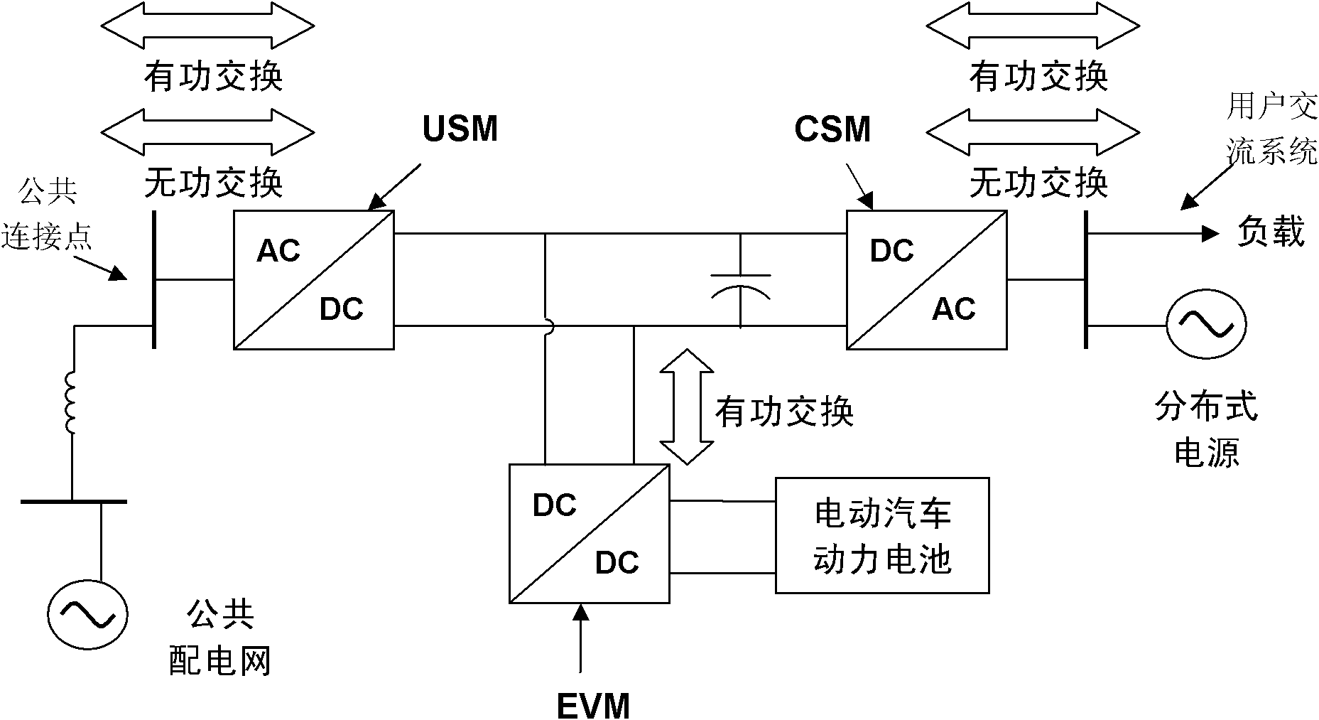
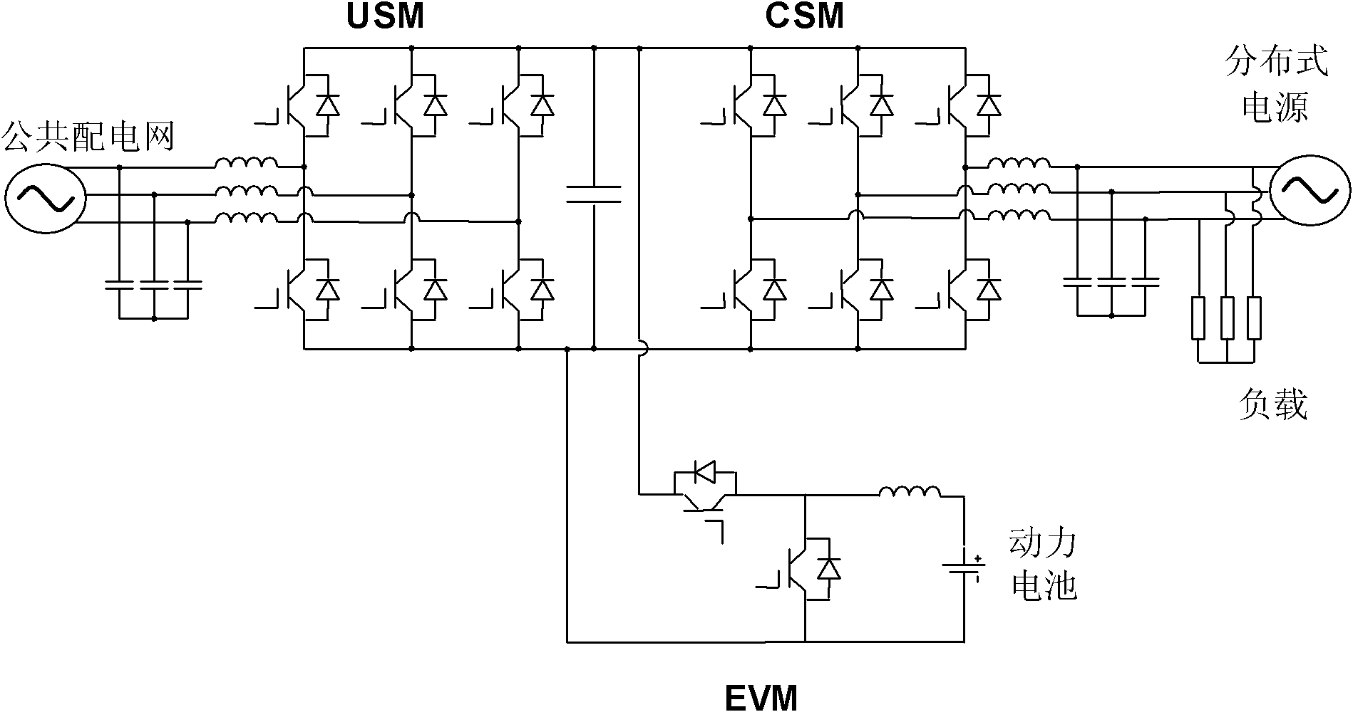
[0030] Such as Figure 1-2 The standardized converter device for electric vehicles and distributed power sources shown is composed of a grid-side power module USM connected to the public distribution network, a user-side power module CSM connected to users, and an electric vehicle charging and discharging module EVM for energy storage , the user-side power module CSM is connected in parallel with the electric vehicle charging and discharging module EVM, and then connected in series with the grid-side power module USM.

[0031] The grid-side power module USM is composed of controllable devices to form a three-phase full-bridge rectifier circuit, which can be connected to the public distribution network through a transformer or directly, and can operate in four quadrants to realize bidirectional control of active power and reactive power with the public distribution network ; The user-side power module CSM is composed of controllable devices to form a three-phase full-bridge inv...


PUM


Abstract

The invention discloses a standardized current conversion device applicable to an electric vehicle and a distributed power source to be accessed to a public power distribution network. The traditional distributed power source can not be effectively isolated from the power network, the requirements of high-end users for power quality can not be ensured, and power users with severe pollution can not be prevented from injecting power into the power network. The standardized current conversion device comprises a power network side module, a user side module, an electric vehicle charging and discharging module and a controller, wherein the network side module is connected with the electric vehicle charging and discharging module in parallel and then is connected with the power network side module in series; a trigger pulse signal generated by the controller is transmitted to the power network side module, the user side power module and the electric vehicle charging and discharging module through optical fibers, the controller communicates with a background server through Ethernet, and a background monitoring software module is installed in the background server. The invention can realize the effective isolation of the distributed power source and the power network and can also combines the functions of dynamic reactive compensation, fault current limitation, power quality control and the like.

Description

technical field [0001] The invention relates to the field of power supply and utilization, in particular to a standardized converter device for electric vehicles and distributed power sources. Background technique [0002] With the continuous expansion of the grid scale, the disadvantages of large-scale power systems are becoming more and more prominent, such as high cost, inflexible operation control, difficulty in adapting to the increasingly high reliability requirements of users, inability to flexibly track load changes and diversified electric energy Quality needs. Scholars began to study the development model of the future power system. Obviously, simply expanding the scale of the power grid cannot meet the requirements. Therefore, European and American power experts proposed a distributed power grid with less pollution, high reliability, low investment, flexible power generation methods, and compatibility with the environment. The way of joint operation of power gene...

Claims


Application Information

Patent Timeline
IPC IPC(8): B60M3/00H02M5/458H02M7/5387H02J7/10H02J7/00H04L29/08
CPCY04S30/12Y02T90/168Y02T90/167
Inventor 陆翌
Owner ELECTRIC POWER RES INST OF STATE GRID ZHEJIANG ELECTRIC POWER COMAPNY
Learn More