
Synergic uplink and downlink transmission method and synergic system between base stations

A technology of cooperative transmission and transmission method, applied in the system field of cooperation between base stations, can solve the problems of inability to realize cross-base station cooperative transmission, unfavorable service quality and throughput, limiting UE communication transmission performance, etc.

Active Publication Date: 2013-09-04
CHINA MOBILE COMM GRP CO LTD
View PDF2 Cites 0 Cited by
  • Summary
  • Abstract
  • Description
  • Claims
  • Application Information

AI Technical Summary

Problems solved by technology

From the analysis of the above example, it can be seen that the intra-site cooperation of only a single base station is far from meeting the performance requirements of the UE, and the performance of the UE located at the edge of the base station will be much lower than that of the UE located in the central area of ​​the base station
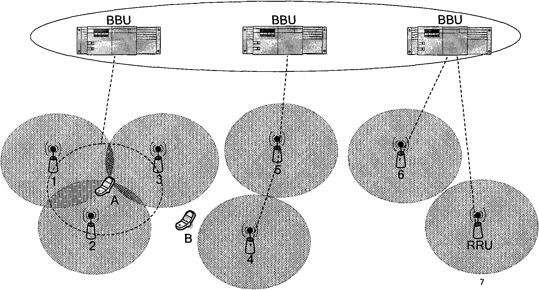
Therefore, the existing intra-site cooperation methods cannot realize cooperative transmission across base stations, and cannot select the cooperative RRU set actually needed according to the specific location of the UE, which limits the communication transmission performance of the UE and is not conducive to improving its service quality and throughput.

Method used


Image

  • Synergic uplink and downlink transmission method and synergic system between base stations
  • Synergic uplink and downlink transmission method and synergic system between base stations
  • Synergic uplink and downlink transmission method and synergic system between base stations

Examples


Embodiment Construction

[0094] In order to make the object, technical solution and advantages of the present invention clearer, the present invention will be further described in detail below with reference to the accompanying drawings and examples.

[0095] The embodiment of the present invention firstly provides a coordinated uplink transmission method between base stations, the process of which is as follows Figure 5 shown, including:

[0096] Step 501: the current primary base station (Anchor Cell) sends an air interface measurement request to UEs located in its cell;

[0097] Step 502: After receiving the air interface measurement request, the UE sends a measurement report to the current master base station;

[0098] After receiving the air interface measurement request, the UE will measure the specified cell parameters of the cell where the UE is currently located and its neighboring cells, and include the measured value in the measurement report and return it to the current main base station...


PUM


Abstract

The invention discloses an uplink transmission method between base stations, comprising the following steps: a current main base station receives a measurement report returned from UE (user equipment) to determine the current synergic RRU (remote radio unit) assembly; when a current synergic RRU assembly has RRU belonging to a synergic base station, the synergic base station requests for received uplink data from the UE from RRU belonging to the synergic base station; and each RRU in the current synergic RRU assembly sends received uplink data from the UE to the current main base station. The invention also discloses a downlink transmission method between base stations, a synergic system between base stations and the base station, which can simultaneously utilize RRU belonging to the synergic base station in the synergic RRU and RRU belonging to the synergic base station to carry out data interaction with the UE when the current synergic RRU assembly has RRU belonging to the synergic base station, thus realizing across-base station synergic transmission for the UE, improving the communication transmission performance and throughput of the UE, and improving service quality for the UE.

Description

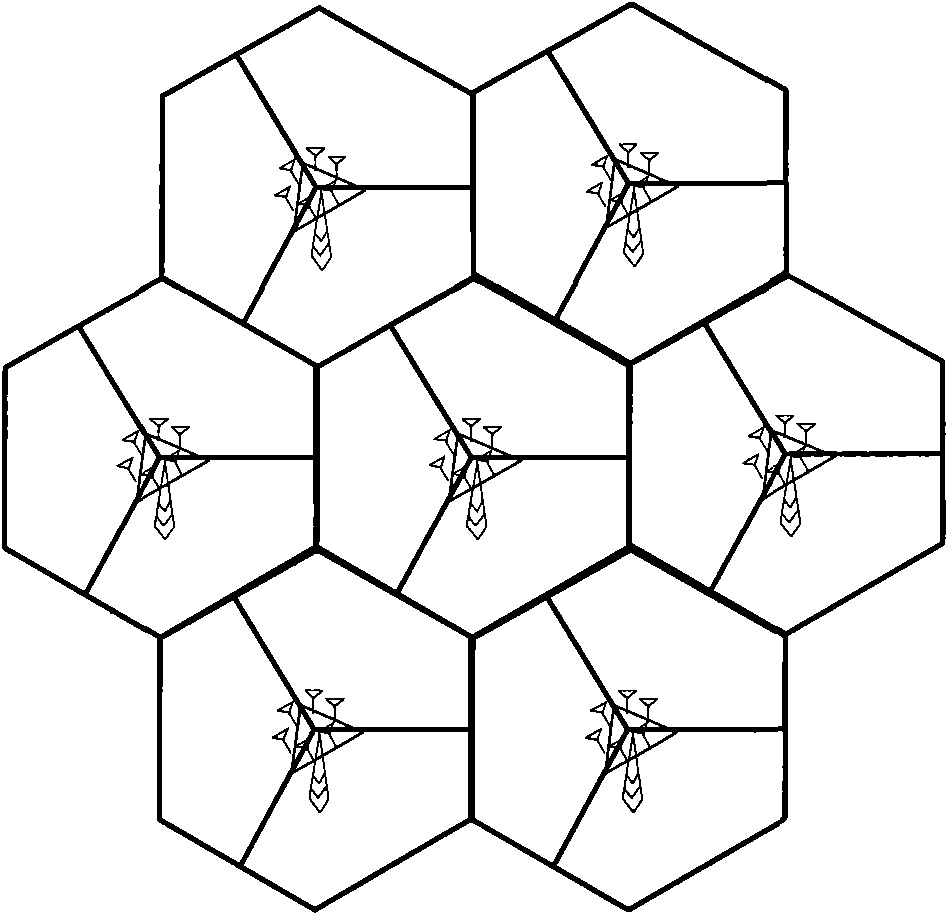
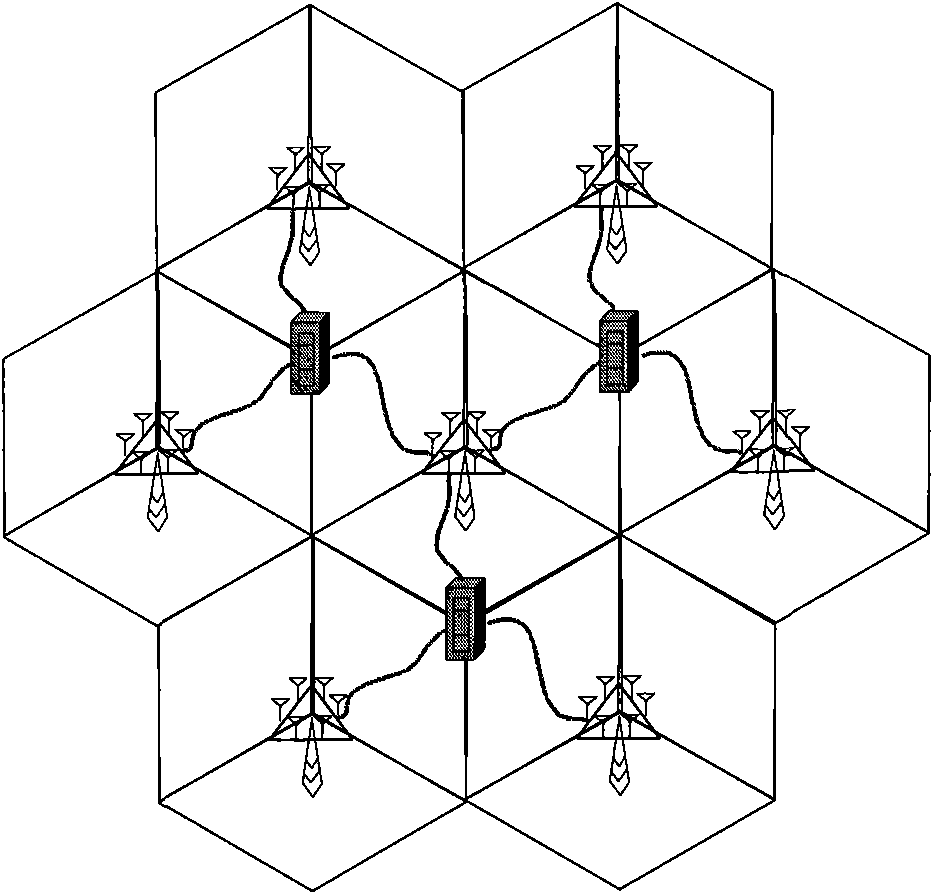
Technical field [0001] The present invention involves mobile communication technology, which specifically involves the upper and downward transmission methods between base stations, as well as systems between base stations. Background technique [0002] In the LONG TERM Evolution-Advanced (LTE-A), the current ORTHOGONAL FREQUENCY DIVIDED MULTIPLESS (OFDMA) technology is currently adopted.The way to distinguish between user devices (UEEQUIPMENT, UE), by carrying different UE information on different carrier of mutual orthodontics, can effectively reduce the adverse effects of frequency selective decline. figure 1 It shows the topology architecture of the honeycomb network used in the current LTE-A system. As shown in the figure, each base station covers a sector (that is, a community). Because the frequency used in different UEs in the community is orthodox, soFor the UE in a community, all their interference comes from other communities, so that this method can greatly improve th...

Claims


Application Information

Patent Timeline
Patent Type & Authority Patents(China)
IPC IPC(8): H04W28/00H04W88/08H04B7/26
Inventor 陈沫闫志刚
Owner CHINA MOBILE COMM GRP CO LTD
Learn More