
Motor vehicle power train

A technology for motor vehicles and drive trains, which is applied to motor vehicles, electric vehicles, hybrid vehicles, etc., and can solve problems such as expensive, complex structures, and difficult manufacturing

Inactive Publication Date: 2014-03-12
VOITH PATENT GMBH
View PDF4 Cites 0 Cited by
  • Summary
  • Abstract
  • Description
  • Claims
  • Application Information

AI Technical Summary

Problems solved by technology

Although recent attempts have been made to drive auxiliary units, such as air-conditioning compressors for passenger cars, by means of a separate electric motor when the internal combustion engine is not running, such a drive is, on the one hand, structurally complex, relatively large in size and difficult to manufacture. is difficult and expensive

Method used

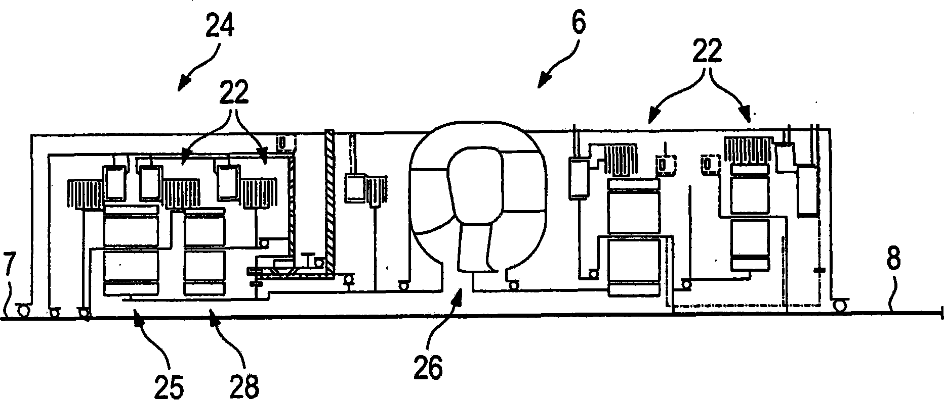
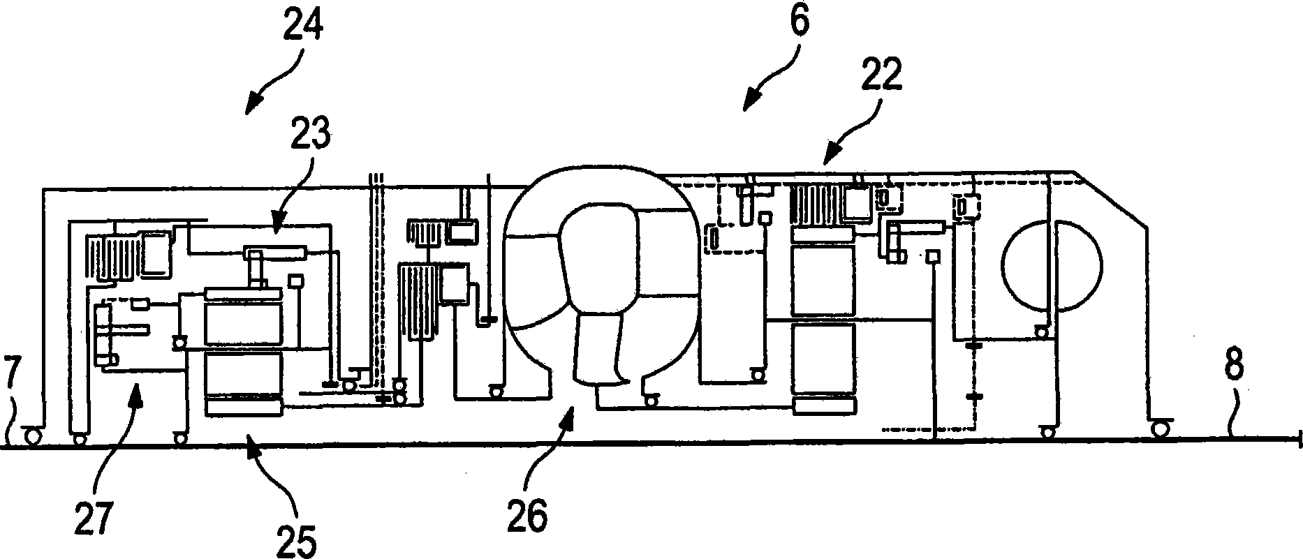

Image

  • Motor vehicle power train
  • Motor vehicle power train
  • Motor vehicle power train

Examples


Embodiment Construction

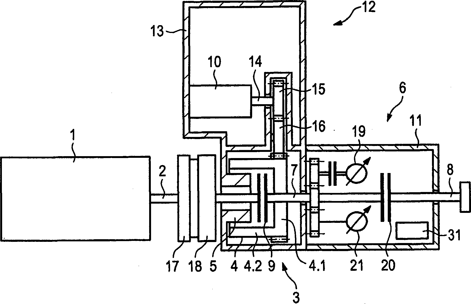
[0024] figure 1A schematic diagram of a first embodiment of a motor vehicle drive train according to the invention is shown. Here, viewed in the direction of power transmission, the following components are connected in series: the main drive motor 1, the driven shaft 2, the flywheel 17, the torsional vibration damper 18, the first separation clutch 9, the electric motor 3 and the first and The gearbox 6 of the second pump 19 , 21 , the second separating clutch 20 and the gearbox output shaft 8 . Currently, the main drive engine 1 is designed as an internal combustion engine and drives the gearbox input shaft 7, the gearbox output shaft 8 of the gearbox 6 and is drive-connected to the gearbox output shaft 8 in a first operating state when the first separating clutch 9 is engaged. A cardan shaft, not shown, drives the drive wheels of the vehicle, also not shown (first power branch). At the same time, the drive power is transmitted via the rotor 4 of the electric motor 3 , whi...


PUM


Abstract

A motor vehicle power train includes a main drive engine with an output shaft for driving the drive wheels of the motor vehicle, an electric motor which includes a rotor and a stator, also for driving the drive wheels of the motor vehicle, an automatic transmission, with a plurality of selectively settable drive connections, a transmission input shaft and a transmission output shaft, the rotor of the electric motor being disposed in a drive connection between the output shaft of the main drive engine and the transmission input shaft, and can be disengaged from the output shaft with a clutch, and at least one ancillary unit which can be driven by the main drive engine. The rotor of the electric motor includes an exterior drive having a gearing of friction surface which has a driving connection to the at least one ancillary unit.

Description

technical field [0001] The invention relates to a drive train of a motor vehicle, in particular a heavy goods vehicle, such as a city bus, for the transport of people or goods. Background technique [0002] Recently, hybrid-drive trucks are known, the drive train of which essentially comprises a main drive motor designed as an internal combustion engine, an electric motor and a gearbox. Furthermore, the internal combustion engine, the electric motor and the transmission are usually arranged consecutively in the direction of power transmission, as viewed from the output shaft of the internal combustion engine to the transmission output shaft. Typically, the internal combustion engine and the electric motor are drivingly connectable to the transmission input shaft for driving the wheels such that the wheels are either driven by the internal combustion engine or the electric motor alone or both. Furthermore, auxiliary units which may be arranged in the drive train are in parti...

Claims


Application Information

Patent Timeline
Patent Type & Authority Patents(China)
IPC IPC(8): B60K6/40B60K6/48B60K6/54
CPCB60Y2200/143B60K6/26Y02T10/6269Y02T10/6221B60K6/48Y02T10/62
Inventor 伯恩哈德·维斯特
Owner VOITH PATENT GMBH
Learn More