
Bias point control device and method of DQPSK (Differential Quadrature Phase Shift Keying) demodulator

A bias point and demodulator technology, applied in the field of optical communication, can solve the problems of inaccurate detection of the minimum peak value of the output voltage signal, large bandwidth, and inability to guarantee the phase deviation of the I arm and the Q arm.

Active Publication Date: 2011-02-16
ZTE CORP
View PDF3 Cites 9 Cited by
  • Summary
  • Abstract
  • Description
  • Claims
  • Application Information

AI Technical Summary

Problems solved by technology

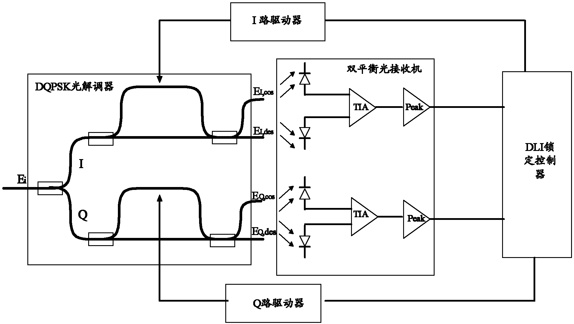
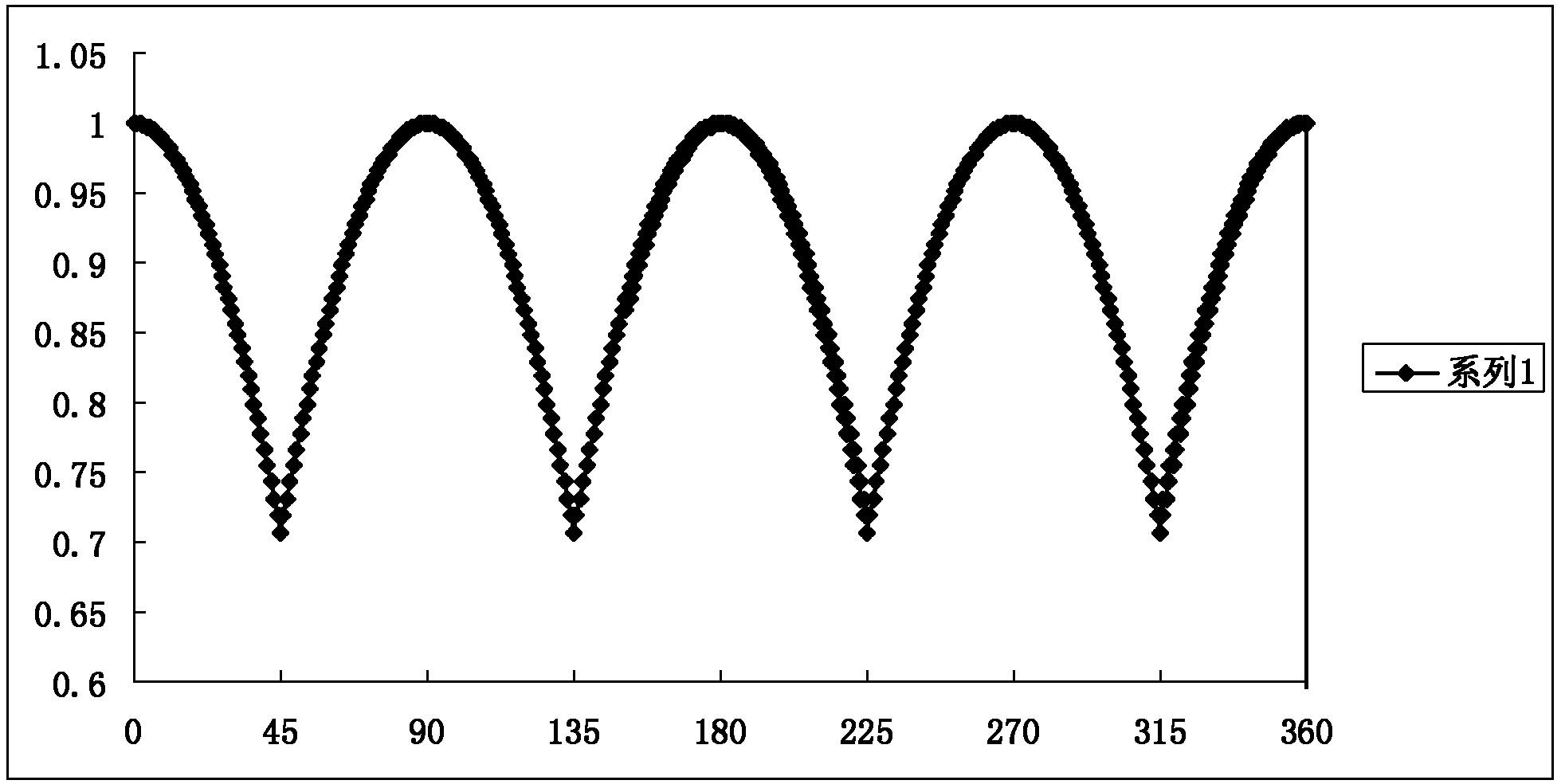
However, there are two problems in this current locking method. One is that the phase deviation between the I arm and the Q arm cannot be guaranteed to be π / 2, so even if the I arm and the Q arm are locked at π / 4 or an odd multiple of π / 4 , since the phase deviation may not be π / 2, the phase of the I arm cannot be π / 4 through the polarity inversion of the output signal of the I arm and the output signal of the Q arm and the exchange of the I arm and the Q arm. The phase is -π / 4; Second, the current minimum detection of the maximum value of the balanced receiver output signal mostly uses the peak detector provided inside the balanced receiver
However, at present, the bandwidth of the peak detector circuit inside the balanced receiver is relatively large, resulting in inaccurate detection of the minimum peak value of the output voltage signal of the balanced receiver, and the DQPSK demodulator cannot lock on the correct bias point.

Method used


Image

  • Bias point control device and method of DQPSK (Differential Quadrature Phase Shift Keying) demodulator
  • Bias point control device and method of DQPSK (Differential Quadrature Phase Shift Keying) demodulator
  • Bias point control device and method of DQPSK (Differential Quadrature Phase Shift Keying) demodulator

Examples


Embodiment Construction

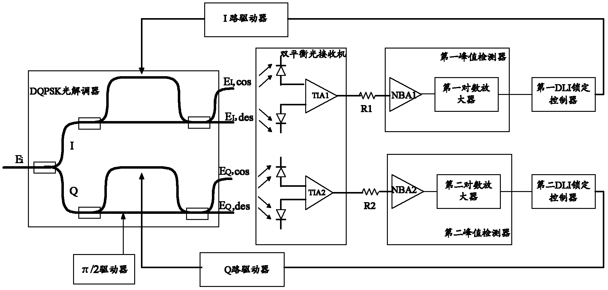
[0039] Embodiments of the present invention provide a DQPSK bias point control method and device, using a π / 2 driver, capable of controlling the phase deviation of the I-way and Q-way to be π / 2, and using a peak detector, which can accurately obtain the double-balanced optical receiver Output the peak signal of the voltage, and use the DLI locking controller to obtain the peak detection error signal according to the voltage peak signal, and adjust the bias point control voltage signal according to the feedback control of the peak detection error signal until the error detection signal is 0, that is, obtain The minimum value of the voltage peak signal, the bias point voltage control signal no longer changes, the DQPSK demodulator will lock the bias of the I signal at π / 4 or an odd multiple of π / 4, and lock the Q signal at π / 4 or an odd multiple of π / 4. And when it is determined that the I-channel signal and the Q-channel signal are not biased at the correct bias point, the pol...


PUM


Abstract

The invention relates to the field of optical communications, in particular to a bias point control device and method of a DQPSK (Differential Quadrature Phase Shift Keying) demodulator, which can accurately acquire the minimum value of a peak value detection signal and lock the DQPSK demodulator to an accurate bias point. The device comprises a sampling resistor, a peak value detector, a DLI (Data Link Interface) locking controller, a driver and a pi / 2 driver, wherein the peak value detector is used for acquiring a voltage peak value signal of a voltage signal according to the voltage signal collected by the sampling resistor, the DLI locking controller is connected with the output end of the peak value detector and outputs a periodic bias point control voltage signal, the input end of the driver is connected with the output end of the DLI locking controller and used for adding the periodic bias point control voltage signal to an I-path signal or Q-path signal of the DQPSK demodulator, the pi / 2 controller is used for adding a third bias point control voltage signal to the Q-path signal of the DQPSK demodulator and controlling the phase difference between the I-path signal and the Q-path signal of the DQPSK demodulator to be pi / 2.

Description

technical field [0001] The invention relates to the field of optical communication, in particular to a device and method for controlling a bias point of a DQPSK demodulator. Background technique [0002] In recent years, with the improvement of the speed and capacity of the optical transmission system, the optical phase modulation method represented by DQPSK has attracted more and more attention from the industry. DQPSK (Differential Quadrature Phase Shift Keying) is a modulation method of differential quadrature phase shift keying. It uses four different phases of light waves to represent different data signals, so its symbol speed is only half of the traditional optical amplitude modulation method. For optical Device requirements are much smaller. In addition, compared with amplitude modulation, DQPSK modulation also has superior dispersion tolerance and polarization mode dispersion tolerance performance, and is more suitable for large-capacity, long-distance optical tran...

Claims


Application Information

Patent Timeline
Patent Type & Authority Applications(China)
IPC IPC(8): H04B10/67H04B10/69
CPCH04B10/677H04B10/691
Inventor 吕书生
Owner ZTE CORP
Learn More