Method and device for determining the rotary position of a rotating element
A technology of rotating elements, rotating positions
- Summary
- Abstract
- Description
- Claims
- Application Information
AI Technical Summary
Problems solved by technology
Method used
Image
Examples
Embodiment Construction
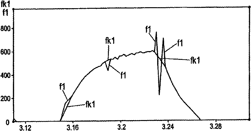
[0040] figure 1 An example of an erroneous frequency waveform f1 as a result of sensorless measurement and an exemplary corrected frequency waveform fk1 are shown. Here, plot the relevant signal amplitude over time.
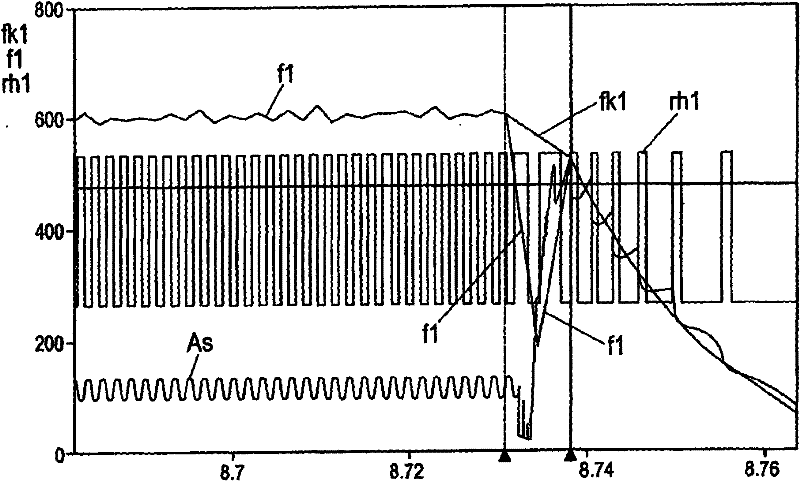
[0041] figure 2 An example of the output signal rh1 of the pulsation counter filter for detecting current pulsation in the armature current As is shown. Here, in addition to the armature current As, the corresponding frequency signal or frequency waveform f1 is also shown, and the corrected frequency signal or corrected frequency waveform fk1 is shown in the area where the error occurs. Here, in this case, the amplitudes of the individual signals over time are shown again.
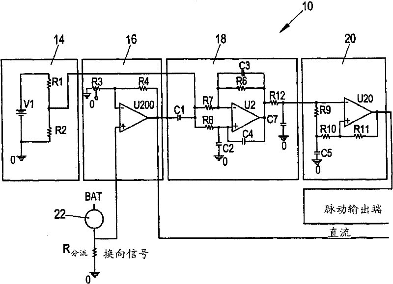
[0042] Related equipment for determining the rotational position of a rotating element assigned to or driven by a motor, especially a DC commutated motor, includes a device for detecting current pulsation contained in the armature current of the motor. Here, the device may include, for example,...
PUM
 Abstract
Description
Claims
Application Information
 - R&D
- Intellectual Property
- Life Sciences
- Materials
- Tech Scout
- Unparalleled Data Quality
- Higher Quality Content
- 60% Fewer Hallucinations
Browse by: Latest US Patents, China's latest patents, Technical Efficacy Thesaurus, Application Domain, Technology Topic, Popular Technical Reports.
© 2025 PatSnap. All rights reserved.Legal|Privacy policy|Modern Slavery Act Transparency Statement|Sitemap|About US| Contact US: help@patsnap.com


