
Mid-span closure method for steel box girder of cable stayed bridge

A technology for steel box girders and cable-stayed bridges, applied to bridges, bridge construction, erection/assembly of bridges, etc., can solve problems such as high risk, dense circumferential welds, and complicated operations, and achieve simple and convenient construction procedures, which are beneficial The effect of structural stress and simplified construction process

Active Publication Date: 2011-01-05
HUNAN ROAD & BRIDGE CONSTR GROUP
View PDF6 Cites 25 Cited by
  • Summary
  • Abstract
  • Description
  • Claims
  • Application Information

AI Technical Summary

Problems solved by technology

This method is complicated to operate, has many auxiliary processes, and has many unsafe factors and high risks. Due to the influence of the space position of the front end of the cantilever beam section at both ends of the closing mouth, too much weight cannot be allocated and the requirement for the rigidity of the skeleton during closing, resulting in When using the previous construction method to close the dragon, the general length of the mid-span closure section (5-7 meters) is much smaller than the length of the standard beam section (generally the standard beam section length is 15 meters), resulting in dense circumferential welds in this section, which has a negative impact on the overall bridge. Unfavorable force

Method used


Image

  • Mid-span closure method for steel box girder of cable stayed bridge
  • Mid-span closure method for steel box girder of cable stayed bridge
  • Mid-span closure method for steel box girder of cable stayed bridge

Examples


Embodiment Construction

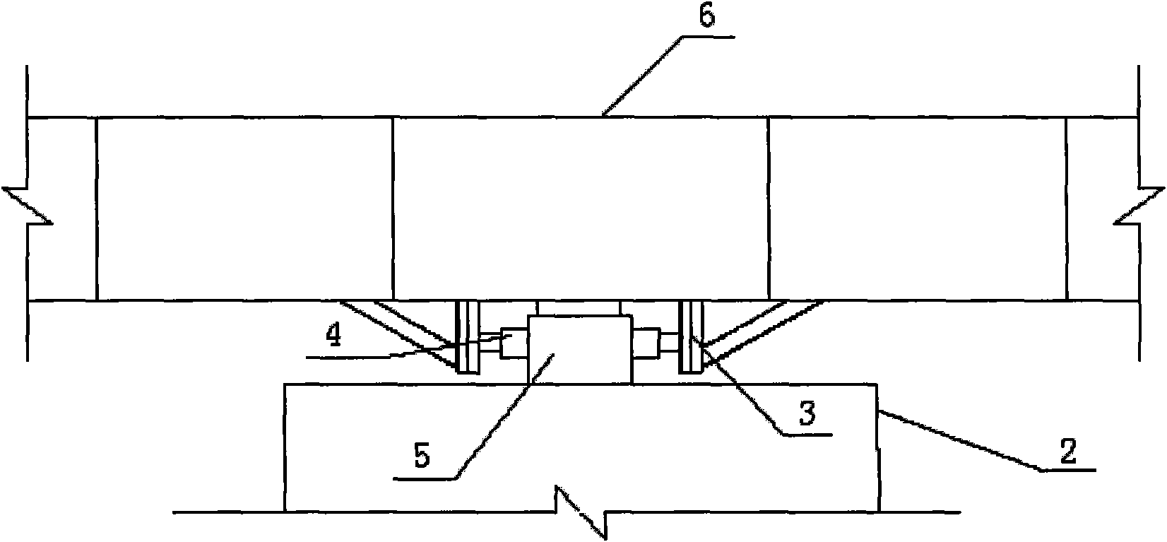
[0013] The construction scheme of the steel box girder mid-span closing method of the cable-stayed bridge of the present invention is as follows figure 1 shown, proceed as follows:

[0014] 1. Complete the installation of the first and second cantilever steel box girders 6 and 10 suspended on the stay cables 8 and located at both ends of the closure;

[0015] 2. Before closing, a longitudinal adjustment device for the width of the closing mouth should be installed between the first cantilever steel box girder 6 of the tower area on the side of the closing mouth and the lower beam 2 of the tower column 1, including: at the bottom of the first cantilever beam section 6 The two reaction force frames 3, the reaction force pier 5 that is located on the lower beam 2 of the tower column 1 and is located between the reaction force frames 3, and the reaction force pier 5 that is located between each reaction force frame 3 and the reaction force pier 5 Self-locking large tonnage jack 4...


PUM


Abstract

The invention discloses a mid-span closure method for a steel box girder of a cable stayed bridge. The method is implemented twice by using splicing of the steel box girder at the closure section and mounted cantilever steel box girder sections at the two ends of a closure opening, and comprises the steps of: during first splicing, mounting a closure opening width longitudinal adjustment device between the first cantilever steel box girder section on one side of the closure opening and a lower cross beam of a lateral tower column, pushing the first cantilever steel box girder section by using the closure opening width longitudinal adjustment device in the same direction, and splicing the steel box girder at the closure section and the second cantilever steel box girder section on the other side of the closure opening by a splicing method for a standard girder section; and during second splicing, pushing the first cantilever steel box girder section by using the closure opening width longitudinal adjustment device in a reverse direction, fixing the relative position between the steel box girder at the closure section and the first cantilever steel box girder section by using a welding seam locking device, and performing welding seam splicing between the steel box girder at the closure section and the first cantilever steel box girder section under an unstressed condition. The method has the characteristics of simple and convenient construction.

Description

technical field [0001] The invention belongs to a bridge construction method, and relates to a mid-span closing method of a steel box girder of a cable-stayed bridge. Background technique [0002] During the construction of the middle span of the known cable-stayed bridge at present, there are mainly two kinds of construction methods, one is the matching and cutting method, and the other is the conventional geometric dimension method. In the implementation process of these two methods, the idea of ​​controlling the closing mouth is used to close the dragon. When closing according to this idea, it is required to accurately adjust and control the relative state of the cantilever beams installed at both ends of the closing mouth before closing. The state of the space position is the same as that after closing the dragon. In order to achieve this purpose, before closing, a counterweight with a total converted weight equal to the weight of the closing section is usually used at ...

Claims


Application Information

Patent Timeline
Patent Type & Authority Applications(China)
IPC IPC(8): E01D21/00E01D21/10
Inventor 欧阳钢方联民裴炳志林立军谢臣万华刘武
Owner HUNAN ROAD & BRIDGE CONSTR GROUP
Learn More