
Self-propelled platform base

A platform and horizontal hydraulic cylinder technology, applied in the base field of self-propelled platforms, can solve problems such as poor passing capacity, complex structural control system, and low work efficiency, and achieve fast response, high control precision, and high work efficiency.

Active Publication Date: 2011-01-05
ZHEJIANG DINGLI MACHINERY CO LTD
View PDF8 Cites 17 Cited by
  • Summary
  • Abstract
  • Description
  • Claims
  • Application Information

AI Technical Summary

Problems solved by technology

[0002] Self-propelled aerial work platforms are widely used in shipbuilding, engineering construction, industrial installation, equipment maintenance and other industries. The ground of these workplaces is generally not flat, and there are obstacles such as potholes, slopes and stones. Traditional rigid self-propelled The off-road ability of the base of the type platform is insufficient, and the four-wheel drive is acceptable. If the two-wheel drive is used, it is basically impossible to apply in this kind of place; and if the distance between the base and the ground is too low, the passing ability is poor and it cannot adapt to obstacles If there are many places, if the distance between the base and the ground is too high, the supporting force for the high-altitude platform will not be enough, and it is prone to rollover and cause accidents
[0003] In order to improve the stability of the high-altitude platform and reduce the possibility of rollover, it is necessary to increase the wheelbase, but the passability of the large wheelbase is poor, and there is a maximum wheelbase requirement for driving on the road, so a retractable wheelbase is required. Reduce the wheel base; recently, most of the bases are in the state of stopping, and the lifting device is used to raise the roof to a certain height, so that the wheels are lifted from the ground and then stretched. After the stretch is in place, the car is put down manually. The work efficiency is low and the structure is complicated.
[0004] Patent No. 200720177872.0 provides a base walking system for high-altitude vehicles. Its wheelbase telescopic mechanism can automatically complete the wheelbase expansion and contraction during driving. The telescopic cylinder is a double-piston rod structure, and the telescopic cylinder is fixed on the base The production and installation of the oil cylinder are complicated, and the base does not adopt a swing bridge structure. When the road is uneven, there will be a phenomenon that the wheels are suspended from the ground, resulting in insufficient driving force.
[0005] Patent Nos. 200820035630 and 200810025198 provide a self-propelled aerial work platform base that can automatically maintain the balance of the hoisting platform. It adopts a double swing bridge structure, but its three-position six-way control valve is installed on the rear axle, and the operation of the control valve The rod is hinged to the rear axle, which makes it difficult to form feedback, and there are deficiencies in action response speed and control accuracy. The expansion and contraction of the wheelbase also uses a jacking cylinder system, which has a complex structure and low work efficiency.
[0006] Patent No. 201010157914 provides a self-propelled aerial work platform vehicle base, which uses a mechanical-hydraulic servo control mechanism to ensure the driving force between the tire and the ground, and can automatically complete the expansion and contraction of the wheel base during driving; but the structure control system is complex

Method used


Image

  • Self-propelled platform base
  • Self-propelled platform base
  • Self-propelled platform base

Examples


Embodiment 1

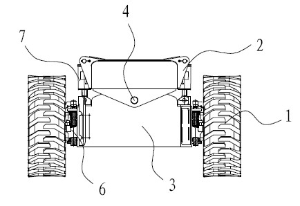
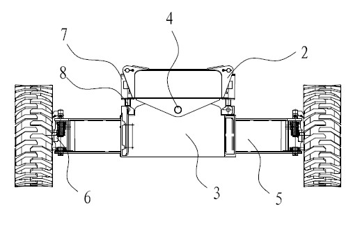
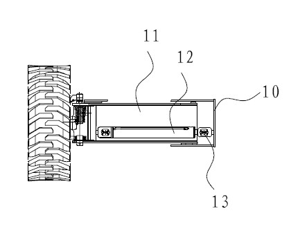
[0032] A self-propelled platform base, comprising a base 2, a level sensor is arranged in the base 2, a swing bridge 3 is hinged on the base 2 through a base spindle 4, a telescopic bridge 5 is installed in the swing bridge 3, and the outer end of the telescopic bridge 5 is provided with Steering structure 6, wheels 1 are installed on the steering structure 6, telescopic bridge chamber 10 is arranged inside, telescopic bridge chamber 10 is provided with telescopic bridge body 11, and telescopic bridge body 11 is fixedly provided with bridge expansion hydraulic cylinder 12, bridge expansion hydraulic pressure The piston end 13 of the cylinder 12 stretches out of the telescopic bridge body 11, tops the inner wall of the telescopic bridge chamber 10, and is fixed on the inner wall of the telescopic bridge chamber 10; the wheel 1 includes a left wheel and a right wheel, and the inner side of the left wheel is provided with a left telescopic bridge. The inside of the right wheel is ...

Embodiment 2

[0036] A self-propelled platform base, comprising a base 2, a level sensor is arranged in the base 2, a swing bridge 3 is hinged on the base 2 through a base spindle 4, a telescopic bridge 5 is installed in the swing bridge 3, and the outer end of the telescopic bridge 5 is provided with Steering structure 6, wheels 1 are installed on the steering structure 6, telescopic bridge chamber 10 is arranged inside, telescopic bridge chamber 10 is provided with telescopic bridge body 11, and telescopic bridge body 11 is fixedly provided with bridge expansion hydraulic cylinder 12, bridge expansion hydraulic pressure The piston end 13 of the cylinder 12 stretches out of the telescopic bridge body 11, tops the inner wall of the telescopic bridge chamber 10, and is fixed on the inner wall of the telescopic bridge chamber 10; the wheel 1 includes a left wheel and a right wheel, and the inner side of the left wheel is provided with a left telescopic bridge. The inside of the right wheel is ...


PUM


Abstract

The invention discloses a self-propelled platform base, which comprises a base, wherein the base is hinged with a swing bridge through a base spindle; wheels are arranged on the two sides of the swing bridge; extension bridges are arranged on the inner sides of the wheels and in the swing bridge and comprise a left extension bridge and a right extension bridge; the wheels include a left wheel and a right wheel; the left extension bridge is arranged on the inner side of the left wheel and the right extension bridge is arranged on the inner side of the right wheel; and the left and right extension bridges are not in the same line. In the invention, as the extension mechanisms of the left and right wheels are not in the same line, wider extension space is formed on the basis of the same base width, and the extended base is wider and more stable, provides a higher strength for supporting an overhead operation platform and lowers tripling possibility; the extension bridge structure can complete extending wheel distance in a running process; the working efficiency is high; and stability and reliability are ensured.

Description

technical field [0001] The invention relates to the field of engineering machinery, in particular to a base of a self-propelled platform. Background technique [0002] Self-propelled aerial work platforms are widely used in shipbuilding, engineering construction, industrial installation, equipment maintenance and other industries. The ground of these workplaces is generally not flat, and there are obstacles such as potholes, slopes and stones. Traditional rigid self-propelled The off-road ability of the base of the type platform is insufficient, and the four-wheel drive is acceptable. If the two-wheel drive is used, it is basically impossible to apply in this kind of place; and if the distance between the base and the ground is too low, the passing ability is poor and it cannot adapt to obstacles In many places, if the distance between the base and the ground is too high, the supporting force for the high-altitude platform is not enough, and it is prone to rollover and cause...

Claims


Application Information

Patent Timeline
IPC IPC(8): B60B35/10B60G17/00
Inventor 许树根
Owner ZHEJIANG DINGLI MACHINERY CO LTD
Learn More