
Circuit arrangement and method for regulating current through at least one discharge lamp

A circuit device and discharge lamp technology, applied in the field of current circuit devices, can solve the problems of large overhead, signal ripple (large fluctuation, slow level change, etc., achieve accurate image color, avoid switching over-oscillation, reduce acoustic effect of noise

Inactive Publication Date: 2010-12-22
OSRAM GMBH
View PDF1 Cites 0 Cited by
  • Summary
  • Abstract
  • Description
  • Claims
  • Application Information

AI Technical Summary

Problems solved by technology

If the RC link is designed so that the time constant τ is small, although the expected value can undergo rapid level changes, the ripple (fluctuation) on the signal is large
Conversely, when τ is chosen large, only slower level changes can be made although the ripple on the lamp current is smaller
In the case of R2R networks for pre-specified expectations, a significant overhead arises: for example, 24 devices are already required to implement an 8-bit R2R network

Method used


Image

  • Circuit arrangement and method for regulating current through at least one discharge lamp
  • Circuit arrangement and method for regulating current through at least one discharge lamp

Examples


Embodiment Construction

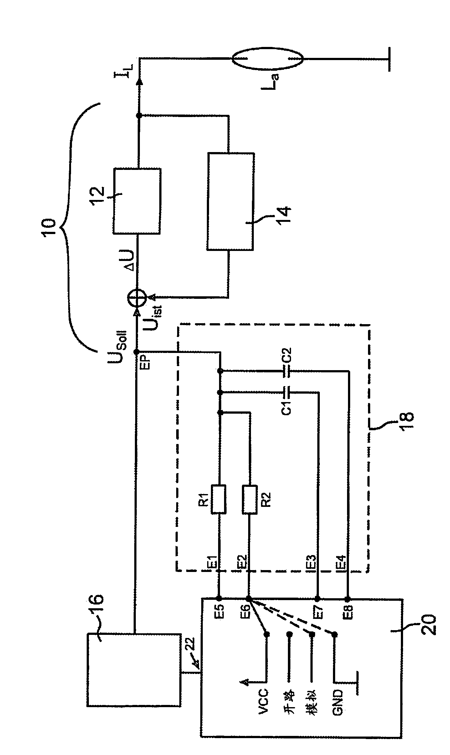
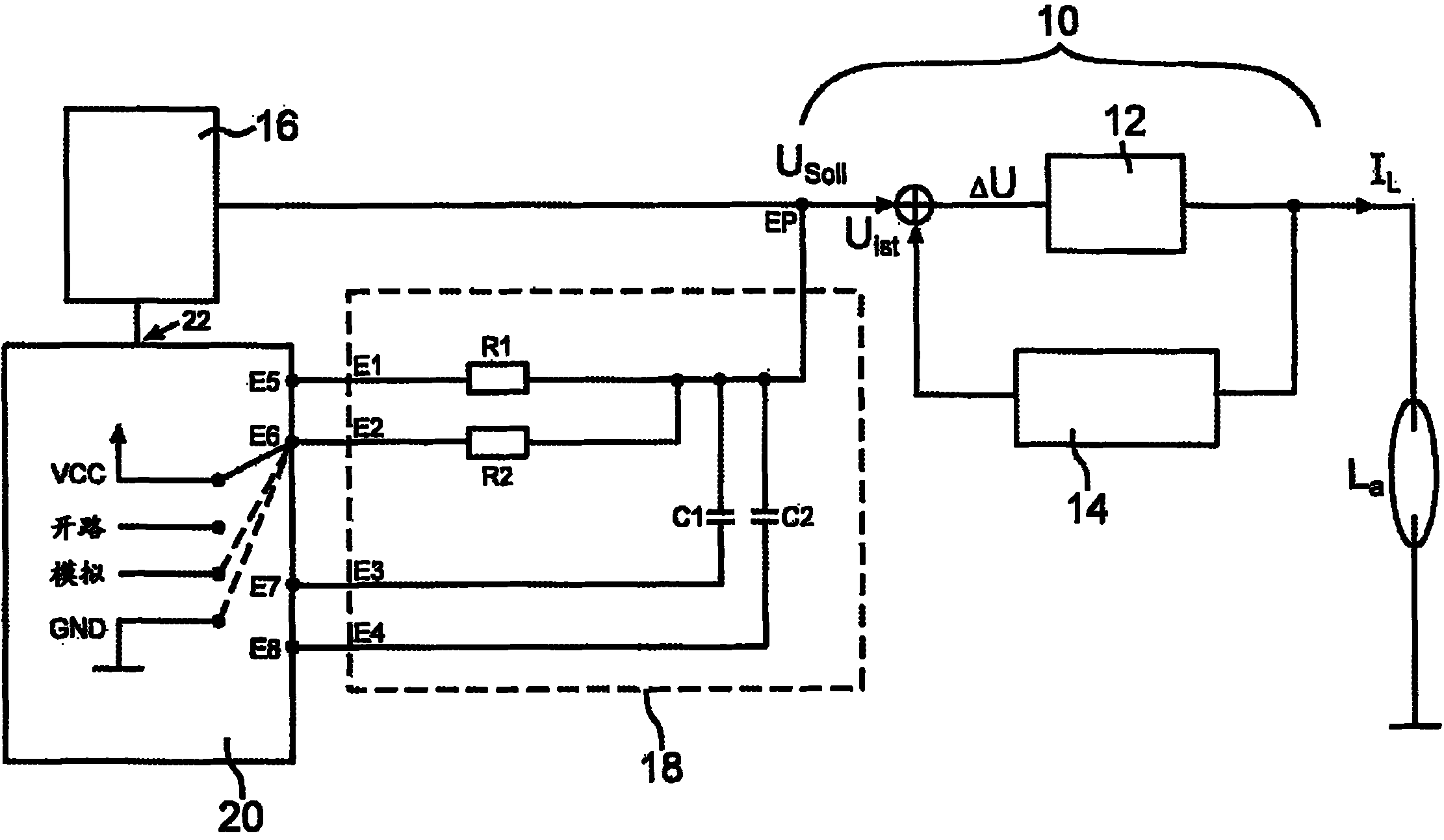
[0019] figure 1 An exemplary embodiment of a circuit arrangement according to the invention is shown in a schematic diagram. The circuit arrangement connects the lamp current I at its output L Provided to the discharge lamp La. The circuit arrangement comprises a control loop 10 whose reference quantity is the desired value U Soll , and its feedback quantity is the actual value U Ist , wherein the adjustment difference ΔU is formed from these quantities by subtraction. The control difference ΔU is supplied to the load circuit 12 of the circuit arrangement, whereby the lamp current I is obtained as output variable of the control circuit 10 L . Actual value U Ist by lamp current I L This is produced by the measuring element 14 , for example by means of a shunt resistor which is arranged at a suitable location in the load circuit.

[0020] also, figure 1 The circuit arrangement includes an excitation device 16, which at its output connects the reference quantity U Soll ...


PUM


Abstract

The present invention relates to a circuit arrangement for regulating the current through at least one discharge lamp having a control loop (10) comprising: a target value input for supplying a target value (UTarget); an actual value input for supplying an actual value (UActual); and an output for providing a signal, which is correlated to the current (IL) through the at least one discharge lamp (La), wherein said actual value (UActual) is correlated with the value of the current through said discharge lamp (La); and a target value preset device (18, 20), which is designed to provide the target value (UTarget) to the control loop (10); wherein said target value preset device comprises: a microprocessor (20) having at least one input (E5; E6; E7; E8), wherein said microprocessor (20) is designed to couple said at least one input (E5; E6; E7; E8) to a potential (VCC; Open; Analog; GND) from a group of at least two different potentials (VCC; Open; Analog; GND); and an interconnection device (18) having at least one input (E1; E2; E3; E4), which is coupled to the at least one input (E5; E6; E7; E8) of the microprocessor (20), and at least one output, which is coupled to at least one point of the control loop (10). In addition, the present invention relates to a corresponding method for regulating the current (IL) through at least one discharge lamp (La).

Description

technical field [0001] The invention relates to a circuit arrangement for regulating the current through at least one discharge lamp, which has a control loop comprising a desired value input for supplying a desired value, an actual value input for supplying an actual value and a control circuit for supplying a desired value. An output for a signal related to the current through the at least one discharge lamp is provided, wherein the actual value is related to the value of the current through the discharge lamp, and the circuit arrangement has a desired value presetting device which is designed to provide the desired value to regulation loop. Furthermore, the invention relates to a method for regulating the current through at least one discharge lamp by means of such a circuit arrangement. Background technique [0002] The invention is concerned with the oscillating system of the lamp current flowing through parasitic components of inductive, capacitive and / or ohmic nature...

Claims


Application Information

Patent Timeline
Patent Type & Authority Applications(China)
IPC IPC(8): H05B41/392
CPCH05B41/3921
Inventor 克里斯蒂安·布罗伊尔马库斯·贝尔马丁·布吕克尔安德烈亚斯·胡贝尔
Owner OSRAM GMBH
Learn More