
Automatic current limiting water saving mouth

A technology of automatic flow limiting and flow limiting seat, which is applied to valve details, engine components, safety valves, etc., and can solve problems such as not being able to automatically throttle and limit flow

Active Publication Date: 2010-12-22
开平市玛格纳卫浴有限公司
View PDF6 Cites 5 Cited by
  • Summary
  • Abstract
  • Description
  • Claims
  • Application Information

AI Technical Summary

Problems solved by technology

The problem is that it can only play the role of filtering, but cannot play the role of automatic throttling and current limiting

Method used


Image

  • Automatic current limiting water saving mouth
  • Automatic current limiting water saving mouth
  • Automatic current limiting water saving mouth

Examples


Embodiment Construction

[0017] The present invention will be further described below in conjunction with the drawings.

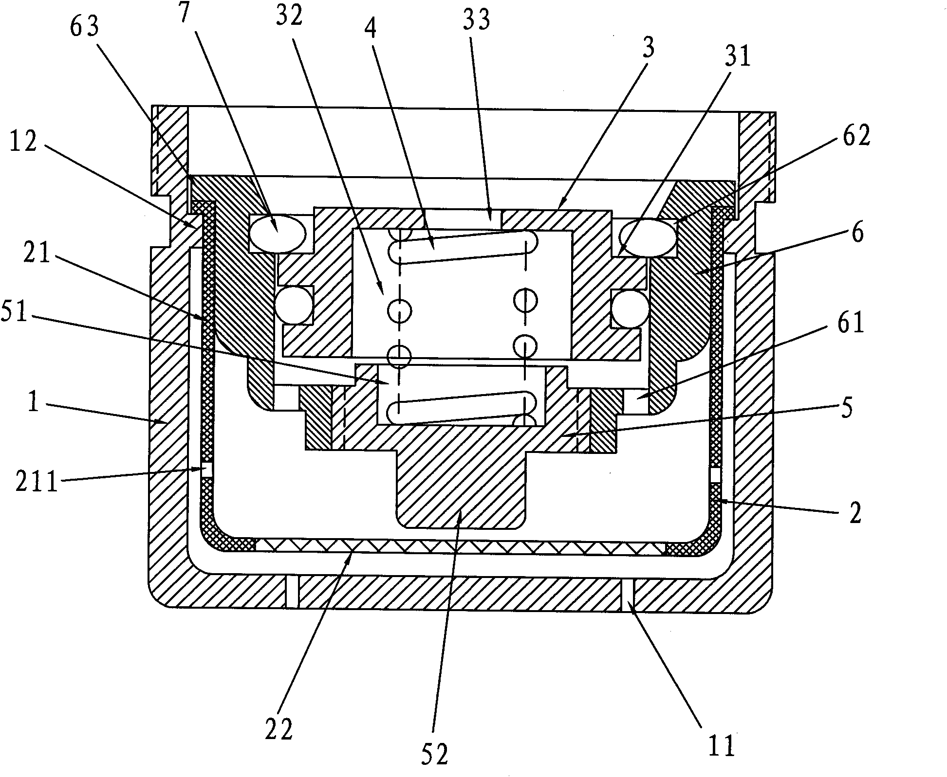
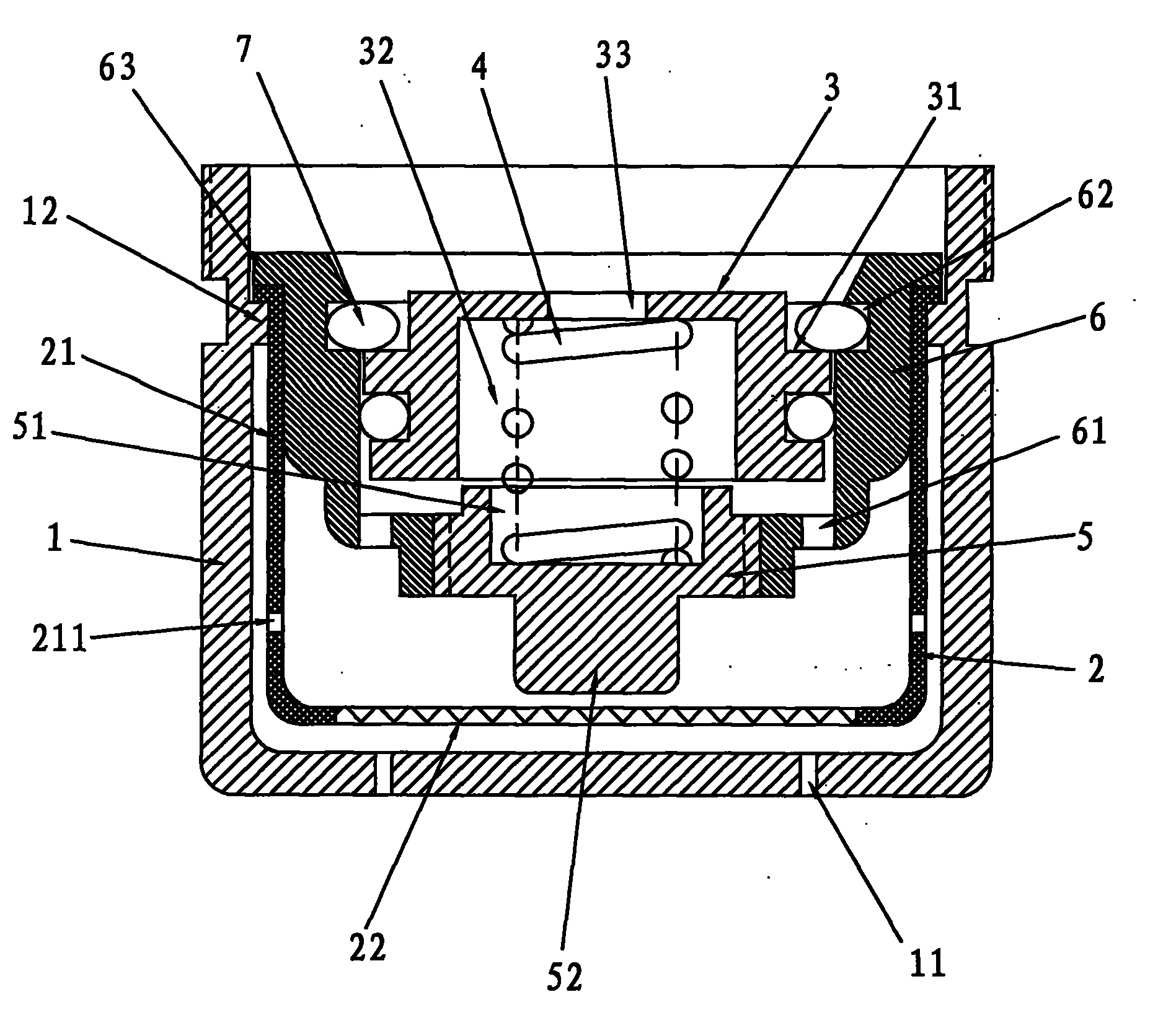
[0018] Such as figure 1 As shown, an automatic flow-limiting water-saving nozzle includes a housing 1 and a filter screen 2. The housing 1 is a cylinder with an open end, the open end is the water inlet, and the bottom plate has a number of water outlet holes 11; it also includes a piston 3 , Pressure spring 4, spring seat 5 and restrictor seat 6;

[0019] There is a circular hole in the center of the bottom of the restrictor seat 6, and there are several water channels 61 surrounding the circular holes at the bottom;

[0020] The piston 3 has an outer ring platform 31 at the upper end, a water outlet cavity 32 at the lower end, and an axial water inlet hole 33 communicating with the water outlet cavity 32;

[0021] The spring seat 5 is detachably connected with the round hole;

[0022] One end of the pressure spring 4 is matched with the spring seat 5, and the other end abuts against the t...


PUM


Abstract

The invention discloses an automatic current limiting water saving mouth comprising a case, a filter screen, a piston, a pressure spring, a spring seat and a current limiting seat, wherein the current limiting seat is provided with a water path; the piston is provided with an external ring table and a water outlet cavity; an axial water inlet is connected with a water outlet cavity; the spring seat and a round hole are connected detachably; the pressure spring is arranged between the top plates of the water outlet cavity of the spring seat; the piston is in slide fit with the inner cavity of the current limiting seat and is sealed by liquid; the inner cavity wall of the current limiting seat is provided with a clamping groove; a notch snap ring is matched with the external ring table and the clamping groove; a gap is detachably arranged between the spring seat and the water outlet cavity; the filter screen is arranged on an internal ring table; the external annular plate of the current limiting seat is pitched on an external folding edge; and the current limiting seat and the filter screen are detachably connected with the case. Because of the structure, the piston moves upwards or downwards according to the pressure of water, the gap between the water outlet cavity of the piston and the barrel of the spring seat is adjudged to obtain the purpose of maintaining normal water yield amount.

Description

Technical field [0001] The invention relates to a device used on a water tap, in particular to a water outlet used on the water outlet of the water tap. Background technique [0002] At present, in the prior art, a water outlet includes a shell and a filter screen. The shell is a cylinder with one end open, the open end is the water inlet, and the bottom plate has a number of water outlet holes, and the filter is arranged in the cylinder of the shell. The problem is that it can only play a filtering role, and cannot play an automatic throttling and current limiting role. Summary of the invention [0003] The purpose of the present invention is to provide an automatic flow-limiting water-saving nozzle, which not only has the function of automatic flow-limiting, but also has the function of filtering water. [0004] The present invention is realized as follows: an automatic flow-limiting water-saving nozzle, including a shell and a filter screen, the shell is a cylinder with an open ...

Claims


Application Information

Patent Timeline
IPC IPC(8): F16K31/122F16K17/20F16K51/00
Inventor 钟国强
Owner 开平市玛格纳卫浴有限公司
Learn More