Powered exercise equipment for use in standing posture
A standing posture and equipment technology, applied in the direction of passive exercise equipment, sports accessories, physical therapy, etc., can solve the problem of not being able to strengthen muscle groups reasonably and effectively
- Summary
- Abstract
- Description
- Claims
- Application Information
AI Technical Summary
Problems solved by technology
Method used
Image


Examples
no. 1 example
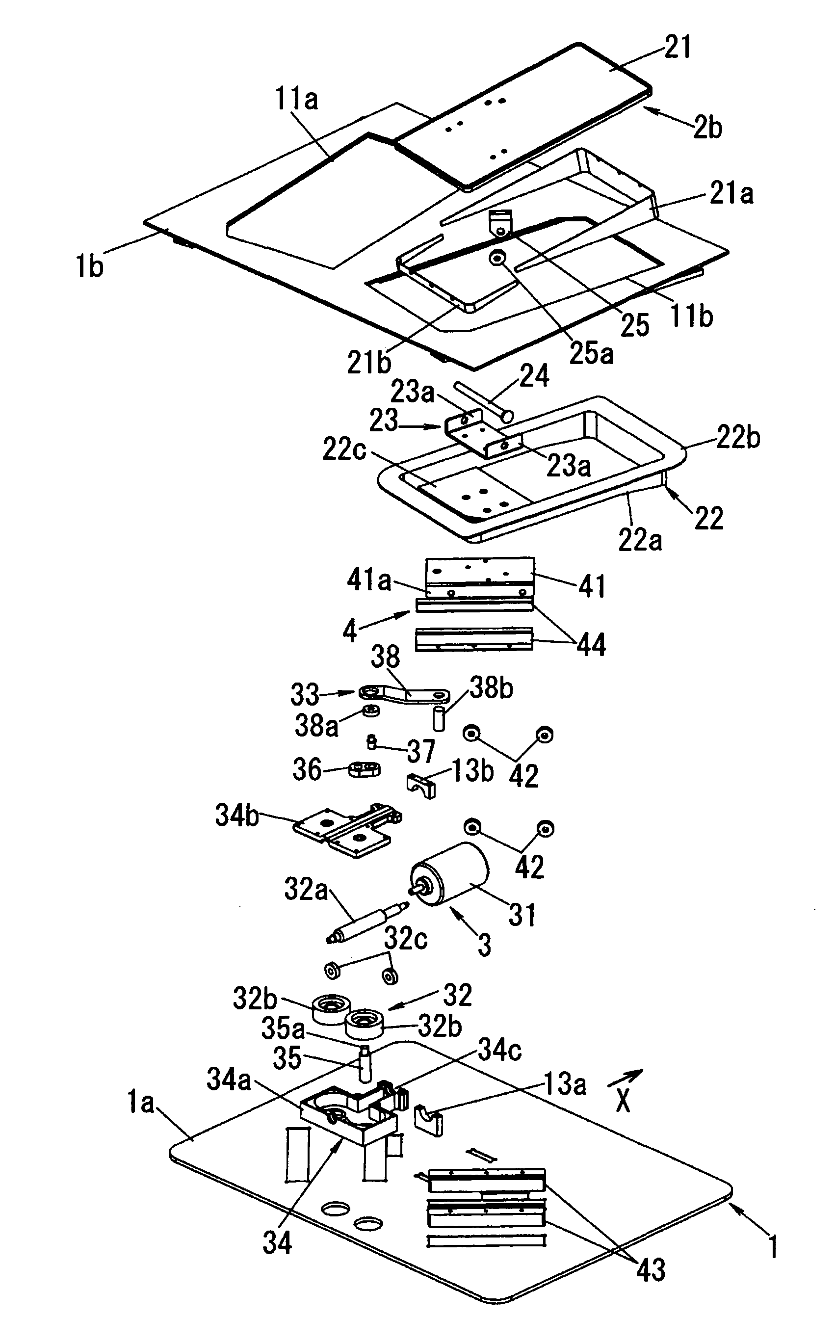
[0033] figure 1 and figure 2 A configuration example as a basic configuration of the present invention is shown. This embodiment is shown in a floor-placed configuration, but an embedded-in-the-floor configuration is only possible. Various options exist, such as configurations that are fixed in place as well as configurations that are removable. The device to be described below can be used with the user sitting on a chair, but is primarily intended for use with the user in a standing position.
[0034] Such as figure 1 and figure 2 As shown, the present embodiment has a base plate 1a as a base frame placed on the floor. The substrate 1a has a rectangular shape, but is not limited to a rectangle. For the sake of simplicity, when the base plate 1a is placed on the floor, the top surface of the base plate 1a is parallel to the floor surface. therefore, figure 1 Up-down in corresponds to up-down in use.
[0035]The upper wall 1b is located above the base plate 1a, and t...
no. 2 example
[0082] Such as Figure 10 As shown, in this embodiment, the footrest board of at least one of the left foot base 2a and the right foot base 2b (only the left foot base 2a is shown in the figure, but can be applied to both of them) 21 is made of deck 51 and footrest board 52. In this configuration, the deck 51 is connected to one end of the crank rod 38 and the footrest board 52 is removably mounted on the deck 51 . The footrest board 52 is removably coupled to the deck 51 . This mode of coupling may be spontaneous, but in this embodiment the deck 51 and footrest plate 52 are secured by set screws 53 threaded through the footrest plate 52 into the deck 51 .
[0083] Cylindrical through-holes 54 into which fixing screws 53 are inserted are arranged in the left-right direction of the footrest board 52 . Therefore, by selecting the through-hole 54 into which the fixing screw 53 is inserted, the position of the footrest board 52 with respect to the table top 51 in the left-right...
no. 3 example
[0086] In the second embodiment, at least one position of the left foot base 2a and the right foot base 2b can be adjusted, but the position of the footrest board 52 relative to the table top 51 is manually adjusted. Such as Figure 11 As shown, in the present embodiment, a range adjuster 5 having a driving source 55 such as a motor is used. Thereby, at least one position of the left foot base 2a and the right foot base 2b can be adjusted without manual operation. Although only one position of the left foot base 2a and the right foot base 2b can be adjusted in this embodiment, both positions are adjusted simultaneously.
[0087] The drive source 55 in the range adjuster 5 adjusts the distance between the left foot base 2a and the right foot base 2b based on information input using the operation input unit 4 having switches (eg, push button switches) and a display device (eg, liquid crystal display). The information inputted by the operation input unit 4 is the attribute of t...
PUM
 Abstract
Description
Claims
Application Information
 - R&D
- Intellectual Property
- Life Sciences
- Materials
- Tech Scout
- Unparalleled Data Quality
- Higher Quality Content
- 60% Fewer Hallucinations
Browse by: Latest US Patents, China's latest patents, Technical Efficacy Thesaurus, Application Domain, Technology Topic, Popular Technical Reports.
© 2025 PatSnap. All rights reserved.Legal|Privacy policy|Modern Slavery Act Transparency Statement|Sitemap|About US| Contact US: help@patsnap.com