Supercharge Your Innovation With Domain-Expert AI Agents!

Fuse attachment structure for vacuum switch

A vacuum switch and installation structure technology, applied in the configuration/arrangement of fuses, switch devices, switch device settings, etc., can solve the problems of unstable contact points, abnormal heating, contact part offset, etc., to achieve high reliability, The error of contact resistance is small, and the effect of stable energized contact

Active Publication Date: 2010-12-08
MITSUBISHI ELECTRIC CORP
View PDF8 Cites 4 Cited by
  • Summary
  • Abstract
  • Description
  • Claims
  • Application Information

AI Technical Summary

Problems solved by technology

The conductive part of the electric fuse 39 and the inner surface of the fuse box 41 appear to be in surface contact with a large area at first glance, but actually it is a plurality of point contacts or line contacts. The state difference makes the contact point not constant, it is difficult to determine which part is in contact
Therefore, there may be a problem that the contact part may deviate and cause abnormal heat generation.

Method used


Image

  • Fuse attachment structure for vacuum switch
  • Fuse attachment structure for vacuum switch
  • Fuse attachment structure for vacuum switch

Examples


Embodiment approach 1

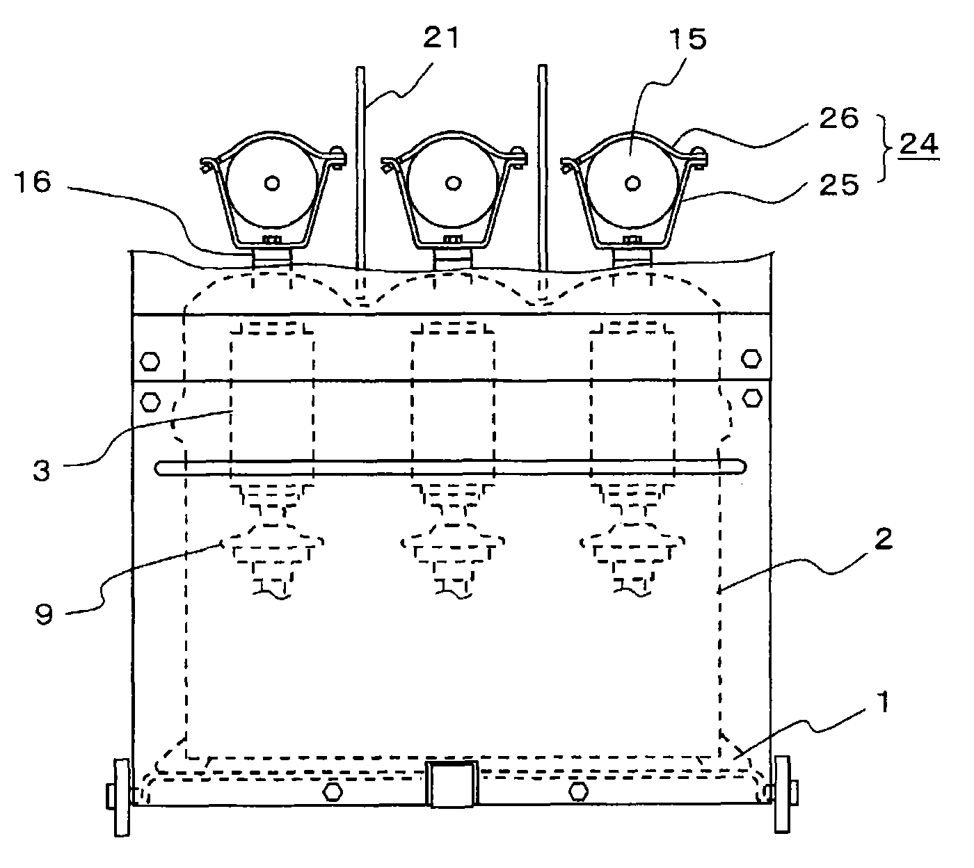
[0051] Hereinafter, the fuse mounting structure of the vacuum switch according to Embodiment 1 of the present invention will be described with reference to the drawings. figure 1 It is a front view of the vacuum switch adopting the fuse mounting structure of Embodiment 1, and shows a state in which a part of the panel on the front side is cut away to see the inside. figure 2 yes figure 1 side view.

[0052] Such as figure 1 and figure 2 As shown, in the insulating frame 2 mounted on the trolley 1, the vacuum interrupters 3 constituting the main circuit contacts of the vacuum switch are arranged in parallel in three phases. The vacuum container of the vacuum interrupter 3 contains a fixed contact 4 and a movable contact 5, the fixed rod 6 is led out from the fixed contact 4, and the movable rod 7 is led out from the movable contact 5 to the outside. The front end side of the fixed rod 6 is connected to the fixed side terminal 8 fixed on the insulating frame 2 , and the...


PUM


Abstract

A fuse attachment structure for vacuum switch for reliably contacting the fuse case and the electric fuse. The inventive fuse attachment structure for vacuum switch has an electric fuse, wherein the fuse case 24 holding and fixing the both ends of the electric fuse 15 is composed of a fuse clip 25 and a fuse push piece 26, the fuse clip has a fixation part 25a fixed on the circuit side and a fuse contact part 25b erecting from both ends of the fixation part 25a in a terminal patulous shape and relatively sloped in a V shape, the fuse push piece 26 connects the two front end parts of the fuse clip 25, and perform force application, to push the electric fuse 15 inserted in the fuse clip 25 to the fuse contact part 25b, and the electric fuse 15 is at least electrically connected to two points abutted to the fuse contact part 25b.

Description

technical field [0001] The invention relates to a fuse installation structure of a vacuum switch with a live fuse. Background technique [0002] Figure 5 Indicates an existing live fused vacuum switch. As shown in the figure, on the frame 31, the vacuum interrupters 32 having fixed contacts and movable contacts (neither of which are shown in the figure) adopt a structure in which three phases are arranged side by side. The movable contact side of the vacuum interrupter 32 is connected to an operating rod 35 attached to an operating shaft 34 via an insulating rod 33 . A movable iron core 36 is provided on the operating shaft 34 , and the movable iron core 36 is attracted by an electromagnet 37 to rotate the operating shaft 34 and drive the operating rod 35 so that the movable contact and the fixed contact contact and separate through the insulating rod 33 . [0003] On the other hand, the fixed contact side is electrically connected to a fixed-side terminal 38 fixed to the...

Claims


Application Information

Patent Timeline
IPC IPC(8): H01H33/66H01H85/22
CPCH01H9/104H01H85/04H01H85/20H01H2207/036H02B1/18H02B13/0354
Inventor 后藤圭二大川义博
Owner MITSUBISHI ELECTRIC CORP
Features
  • R&D
  • Intellectual Property
  • Life Sciences
  • Materials
  • Tech Scout
  • Unparalleled Data Quality
  • Higher Quality Content
  • 60% Fewer Hallucinations
Learn More