
Control method of flame indication module of cookers

A technology of indicating module and control method, applied in the direction of combustion method, electrical program control, program control in sequence/logic controller, etc., can solve problems such as false flame signal, shortened service life, user trouble, etc.

Active Publication Date: 2010-12-08
BSH ELECTRICAL APPLIANCES JIANGSU
View PDF5 Cites 2 Cited by
  • Summary
  • Abstract
  • Description
  • Claims
  • Application Information

AI Technical Summary

Problems solved by technology

[0003] However, during the use of the cooker, if there is wind blowing the flame, or water overflows when cooking food, it may cause the flame to deviate from the flame detection module in a short time, so that the wrong flame signal given by the flame detection module will cause the flame The indicator light is extinguished when the flame is still burning, which brings trouble to the user, and at the same time, because the flame indicator light flickers on and off, its service life is shortened

Method used


Image

  • Control method of flame indication module of cookers
  • Control method of flame indication module of cookers
  • Control method of flame indication module of cookers

Examples


Embodiment Construction

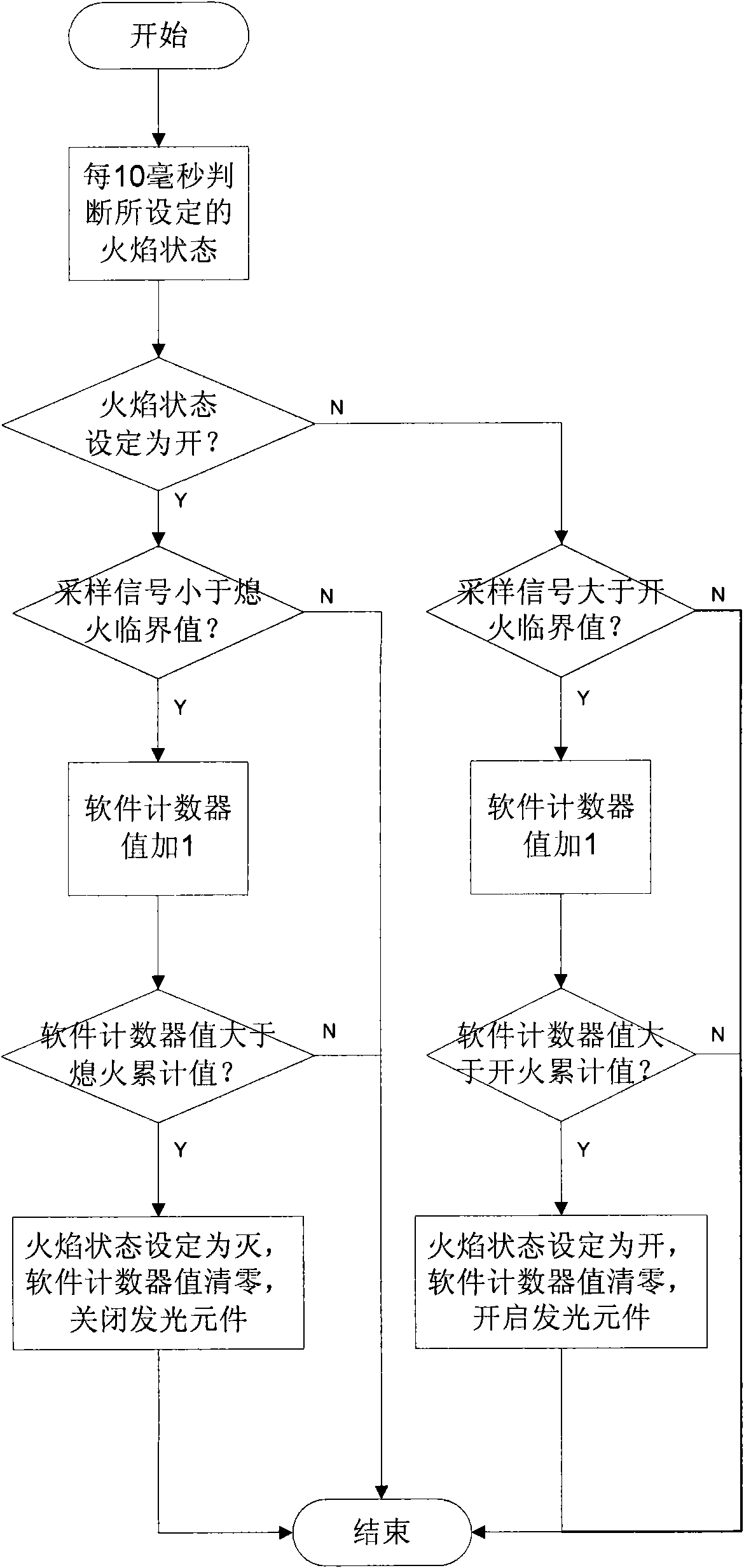
[0015] Such as figure 1 As shown, the cooker flame indicator module 2 includes a flame detection device 4 installed near the burner, and the flame detection device 4 is connected to a controller 10 through a signal amplification device 6 . The controller 10 includes an A / D conversion circuit 8 . A light emitting element 12 is connected with the controller 10 and is controlled by the controller 10 . The light-emitting element 12 is mounted on the cooker at a position convenient for the operator to observe, and displays whether the flame is burning or not. Preferably, the flame detection device 4 is a thermocouple.

[0016] During the working process, the thermocouple 4 produces a change of thermoelectric potential with the change of temperature. The signal amplifying device 6 amplifies the voltage on the thermocouple 4 and converts it into a digital signal recognizable by the controller 10 through the A / D conversion circuit 8 .

[0017] Such as figure 2 As shown, during t...


PUM


Abstract

The invention relates to a control method of a flame indication module of cookers. A voltage analogue signal on a flame detecting device close to a furnace head is amplified via an amplifying device, then the signal is converted into a digital signal via an A / D conversion circuit; a controller collects the digital signal in every other sampling period; the collected digital signal is compared with a flameout critical value; when the digital signals collected in pre-set collecting times are lower than the flameout critical value, the controller closes a light-emitting element. According to thecontrol method, when the flame leaves the flame detecting device for a certain time, the signal collected by the controller is lower than the flameout critical value in the set time, then the flame is judged to extinguish, and the light-emitting element is closed; when the flame deviated caused by wind or spilling water, etc is recovered soon, if the pre-set valve is appropriate, an error indication of the light-emitting element is not existed.

Description

technical field [0001] The present invention relates to a method for controlling a flame indicating module of a cooker, in particular to a method for controlling the opening or closing of a flame indicating lamp according to the state of the flame, wherein the flame indicating module of a cooker includes a flame detection device installed near the burner, which is passed through a signal amplifying device It is connected with a controller, and a light-emitting element is connected with the controller. Background technique [0002] Common cookers need to ignite gas when they are in use, and use the flame to heat the cooking tools. In order to understand the burning state of the flame conveniently and intuitively, a flame indicator light can be installed on the cooker at a position that is convenient for observation. The turning on and off of the flame indicator light is controlled by a flame detection module that can sense whether the flame exists or not. Then the operator c...

Claims


Application Information

Patent Timeline
Patent Type & Authority Applications(China)
IPC IPC(8): F23M11/04G05B19/04
Inventor 潘邦延娄文卿鲁晔张姝雯
Owner BSH ELECTRICAL APPLIANCES JIANGSU
Learn More