Elevator device

An elevator and car technology, applied in the field of elevator installations, can solve problems such as increased deceleration and passenger discomfort

Active Publication Date: 2010-12-01
MITSUBISHI ELECTRIC CORP
View PDF6 Cites 5 Cited by
  • Summary
  • Abstract
  • Description
  • Claims
  • Application Information

AI Technical Summary

Problems solved by technology

[0004] However, in the above-mentioned elevator device, although the car can be prevented from colliding with the terminal portion, there is a problem that although the safety of passengers can be ensured as long as the impact when the car collides with the buffer is within a predetermined value, there is such a problem. Problem: The deceleration of the car needs to be increased more than necessary, causing discomfort to the passengers in the car

Method used


Image

  • Elevator device
  • Elevator device
  • Elevator device

Examples


Embodiment approach 1

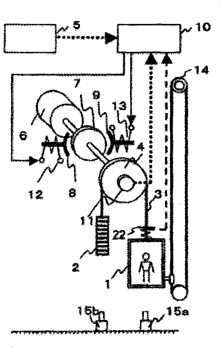
[0017] use figure 1 , the overall structure of the elevator in this embodiment will be described. A hoisting rope 3 that connects the car 1 that moves up and down in the hoistway and the counterweight 2 is wound around a sheave 4 that is rotated by a hoisting machine 6 . During normal operation, the sheave 4 is rotated by the hoisting machine 6 according to a command from the elevator control device 5 . The hoisting rope 3 is moved by the frictional force generated between the sheave 4 and the hoisting rope 3 , so that the car 1 and the counterweight 2 connected by the hoisting rope 3 travel.

[0018] In the brake device, the brake bushes 8 , 9 are pressed against the brake pulley 7 which is fixed to the sheave 4 and rotates by the urging force of the elastic body constituted by the brake spring. Therefore, a frictional force is generated between the brake wheel 7 and the brake bushes 8 , 9 , and the brake bushes 8 , 9 brake the brake wheel 7 . The hoisting machine 6 and th...

Embodiment approach 2

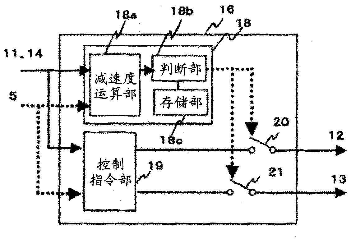
[0039] The brake control device 16 in this embodiment is based on the speed of the car 1 obtained from the car running information collection units such as the hoisting machine encoder 11, the speed limiter 14, and the position sensor at each time, and the speed from the car 1 to the buffer zone. Whether the collision speed of the car 1 can be decelerated to a predetermined speed or not is determined by the remaining distance of the relay 15 (hereinafter referred to as the remaining distance), and the opening and closing of the safety relays 20 and 21 are instructed.

[0040] use Figure 4 , the structure of the brake control device 16 in this embodiment will be described. The brake control device 16 receives (i) the speed of the car 1 obtained from the car travel information collection units such as the hoisting machine encoder 11, the speed limiter 14, and the position sensor, information on the remaining distance, etc. From the elevator control device 5, indicating that it...


PUM


Abstract

An elevator device includes: a car (1) that moves up and down in an elevator shaft; a buffer (15) that stops the car (1) in an elevator shaft end part; brakes (7, 8 and 9) that brake running of the car (1), car running information collecting means that collects information about the running of the car; and brake controlling means (10) that controls the brakes (8 and 9) so that collision speed at the time of collision of the car (1) against the buffer (15) is a prescribed speed or less in order that collision at the time of collision of the car (1) against the buffer (15) falls within a prescribed value on the basis of information collected by the car running information collecting means.

Description

technical field [0001] The present invention relates to an elevator apparatus having a braking device for braking a car in an emergency. Background technique [0002] For a conventional braking device for braking an elevator car, see Japanese Patent Application Laid-Open No. 7-206288. The elevator apparatus described in Japanese Patent Application Laid-Open No. 7-206288 can prevent the car from colliding with the terminal portion by increasing the deceleration of the car near the terminal floor of the hoistway. [0003] Patent Document 1: Japanese Patent Application Laid-Open No. 7-206288 [0004] However, in the above-mentioned elevator device, although the car can be prevented from colliding with the terminal portion, there is a problem that although the safety of passengers can be ensured as long as the impact when the car collides with the buffer is within a predetermined value, there is such a problem. Problem: The deceleration of the car is increased more than necess...

Claims


Application Information

Patent Timeline
Patent Type & Authority Applications(China)
IPC IPC(8): B66B1/32
CPCB66B1/32
Inventor 近藤力雄木川弘
Owner MITSUBISHI ELECTRIC CORP
Why Eureka
Try Eureka