
Warp knitting machine

A warp knitting machine and frame technology, applied in the field of warp knitting machines, can solve the problems of troublesome installation and large number of single parts, etc.

Active Publication Date: 2013-04-17
KARL MAYER STOLL R&D GMBH
View PDF3 Cites 0 Cited by
  • Summary
  • Abstract
  • Description
  • Claims
  • Application Information

AI Technical Summary

Problems solved by technology

The defect of this back-moving spring device is that the number of individual parts is large, and the installation is troublesome.

Method used


Image

  • Warp knitting machine
  • Warp knitting machine
  • Warp knitting machine

Examples


Embodiment Construction

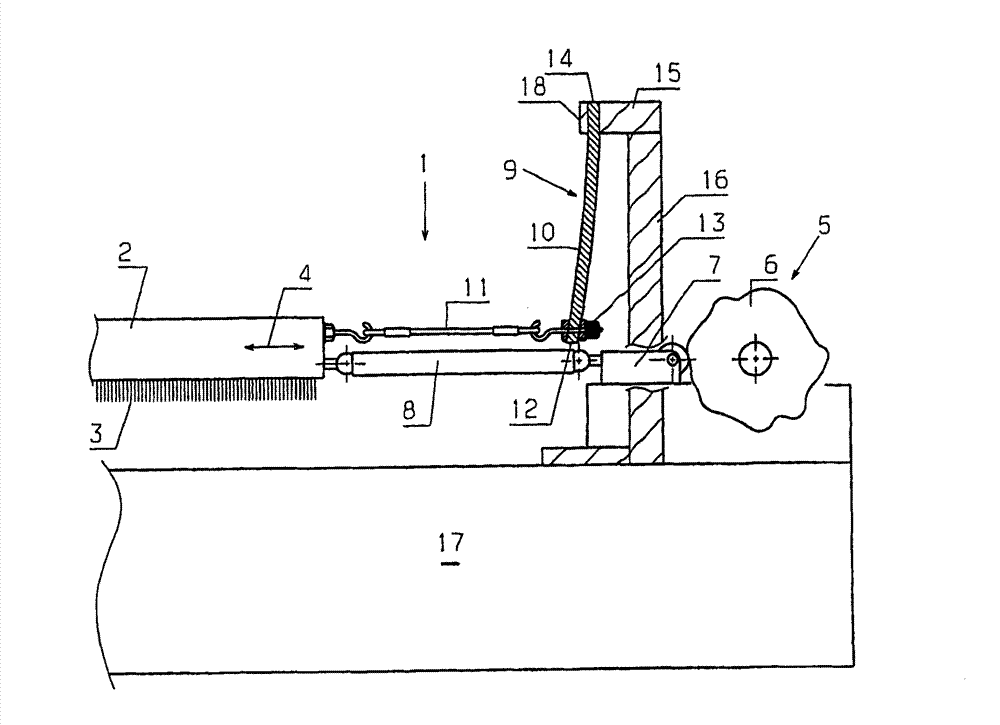
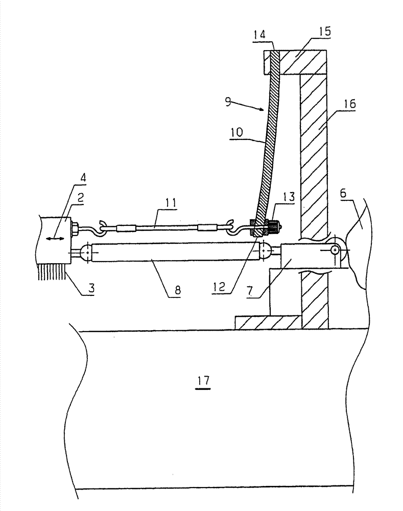
[0025] figure 1 A section of the warp knitting machine 1 is shown in extremely simplified form. Only the yarn guide bar 2 with the yarn guide needle 3 is shown in the figure. For the sake of simplicity, the needle bar and other bars with knitting needles are not shown in the figure.

[0026] During operation, the thread guide bar 2 must be moved back and forth in the traverse direction 4 , that is to say parallel to the longitudinal direction of the thread guide bar 2 . The traversing direction 4 is indicated by a double arrow. Furthermore, as is known per se, the thread guide bar 2 for loop formation is deflected back and forth perpendicular to the plane of the drawing. For the sake of brevity, the means for causing the above-mentioned movements are also not shown in the figure.

[0027] The movement in the traversing direction 4 , hereinafter also referred to as “traversing movement”, is brought about by the thread guide bar drive 5 , which has a jacquard disc 6 , which ...


PUM


Abstract

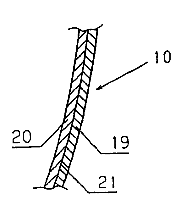
The machine (1) has a guide bar (2), and a guide bar drive acting on the guide bar in a misalignment direction. A reset spring device (9) includes a leaf spring (10) whose one end (14) is fastened to a machine frame (17) and another end (12) is connected with the guide bar by a set screw (13). The spring device is made of fiber-reinforced plastic that exhibits glass fibers. The former end of the leaf spring is fastened to a support (16) of the machine frame by a spacer piece (15). A tension element (11) is provided between the guide bar and the leaf spring.

Description

technical field [0001] The invention relates to a warp knitting machine with at least one thread guide bar, a thread guide bar drive acting on the thread guide bar in the direction of traversing, and a return spring arrangement. Background technique [0002] A warp knitting machine of this type is known, for example, from DE 38 28 469 C2. The thread guide bar drive is here formed, for example, by a cam which acts on the thread guide bar via a push rod. The return spring device makes the yarn guide bar and the push rod lean against the cam all the time. [0003] DE 298 20 527 U1 discloses a similar design. Here too, the thread guide bar drive is formed by a cam disc, which acts on the thread guide bar via a push rod. The return spring device is connected to a return lever, which in turn is connected to the thread guide bar via a traction element and serves to keep the push rod in constant contact with the cam. [0004] The return spring arrangement serves to maintain the ...

Claims


Application Information

Patent Timeline
Patent Type & Authority Patents(China)
IPC IPC(8): D04B27/24D04B27/26
CPCD04B27/26
Inventor M·莱因韦伯M·莫瑟O·弗兰克
Owner KARL MAYER STOLL R&D GMBH
Learn More