
Sand-stone separator

A technology of sand and gravel separator and separation cylinder, which is applied in the field of sand and gravel separator, can solve the problems of limited separation effect, environmental pollution, low export, etc. Effect

Inactive Publication Date: 2010-11-10
曹玉梅
View PDF8 Cites 11 Cited by
  • Summary
  • Abstract
  • Description
  • Claims
  • Application Information

AI Technical Summary

Problems solved by technology

[0003] During the production of ready-mixed concrete, a large amount of waste water and waste residues are produced, and these waste water and waste residues are usually discharged directly without treatment, causing serious pollution to the environment
The existing concrete cleaning and separation equipment has limited separation effect on solids and liquids, and it is difficult to completely separate sand and stones. Not only cannot the recycling of sand and stones be completed, but also the recycling of slurry water, sand and stones cannot be realized, which wastes resources and pollutes the environment.
[0004] In addition, in the process of concrete transportation, residual concrete of mixing equipment, production and construction, it is inevitable to produce excess concrete and disposal of exhausted concrete that cannot be used due to quality problems. According to statistics On average, every 100 cubic meters of concrete produced will produce 1 to 1.4 cubic meters of waste concrete. That is to say, if these waste concrete are not recycled, it will not only cause a lot of waste of resources, but also pollute the environment and cause public nuisance
The exit of the existing sand and gravel separator is low, easy to block, difficult to disassemble and maintain, easy to block, corrode and damage the inside, and has a low service life

Method used


Image

  • Sand-stone separator
  • Sand-stone separator
  • Sand-stone separator

Examples


Embodiment Construction

[0030] The present invention will be further described below in conjunction with accompanying drawing:

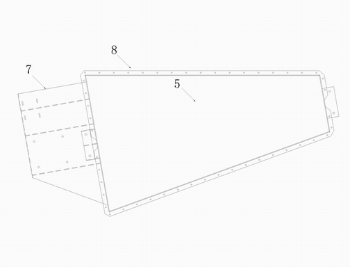
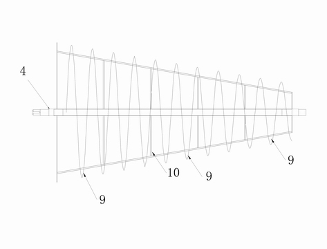
[0031] A sand and gravel separator, comprising a drive motor 1, a conical separation cylinder 5 and a spiral blade 9, the drive motor 1 is connected to one end of the blade shaft 4 through a reduction device 2, and the other end of the blade shaft 4 is connected to the conical separation cylinder 5 rotating connection, the blade shaft 4 is provided with a plurality of helical blades 9 that are conical as a whole, the helical blades 9 are gradually narrowed in the direction of advancement, and the outer cover of the helical blades 9 is provided with a conical separation cylinder 5; the conical separation cylinder 5 The outlet at the front end is connected with the inlet at the rear end of the screening drum 14 correspondingly. The sieving cylinder 14 is a grid-shaped cylinder, and its outlet is placed inclined downwards.

[0032] The cylinder wall rear end feed inlet of sep...


PUM

PropertyMeasurementUnit
Wall thicknessaaaaaaaaaa

Abstract

The invention relates to a sand-stone separator, and is characterized in that the sand-stone separator comprises a drive motor, a tapering separating barrel and helical blades, wherein the drive motor is connected with one end of a blade shaft through a reducing gear, and the other end of the blade shaft is connected with the tapering separating barrel in a rotating mode; the blade shaft is provided with a plurality of the helical blades which present in a tapering shape as a whole; the helical blades gradually shrinks along the propulsion direction, and the tapering separating barrel is sheathed outside the helical blades; the front outlet of the tapering separating barrel is correspondingly jointed with the rear inlet of a screening barrel; the screening barrel is a grid-shaped barrel body, and the outlet thereof is arranged in a downward sloping mode. The sand-stone separator of the invention can separate the sand-stone more thoroughly, has higher working efficiency, enables wastewater and slurry water to be recycled by separating and recovering the sand-stone, has thorough recovering effect, reduces resource waste, and greatly reduces production cost, truly reaching the environmental requirements of zero removal and transportation, no emission and no pollution.

Description

technical field [0001] The invention relates to a mixing and separating device, in particular to a sand and gravel separator for separating and recycling waste water and waste residue produced by ready-mixed concrete. Background technique [0002] Ready-mixed concrete refers to cement, aggregates, water, admixtures, mineral admixtures and other components that are mixed according to needs in a certain proportion, and is sold at the mixing station after being measured and mixed, and is sold by transport vehicles. Concrete mix transported to the place of use within the specified time. [0003] A large amount of waste water and waste residues are generated during the production of ready-mixed concrete. These waste water and waste residues are usually discharged directly without treatment, causing great pollution to the environment. The existing concrete cleaning and separation equipment has limited separation effect on solids and liquids, and it is difficult to completely sepa...

Claims


Application Information

Patent Timeline
IPC IPC(8): B03B5/56
Inventor 李瑞亨
Owner 曹玉梅
Learn More