
Communication system

A communication system and communication network technology, applied in the field of priority control, can solve problems such as unfairness, queues, and difficult users, and achieve the effect of eliminating the sense of unfairness, improving fairness, and ensuring fairness.

Inactive Publication Date: 2010-10-27
HITACHI LTD
View PDF2 Cites 0 Cited by
  • Summary
  • Abstract
  • Description
  • Claims
  • Application Information

AI Technical Summary

Problems solved by technology

However, the larger the network, the more users are accommodated. Therefore, it is difficult to have a queue for each user, and the scalability is limited by the number of queues.
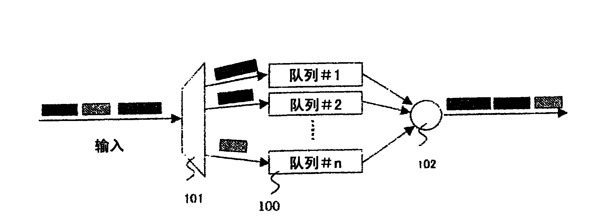
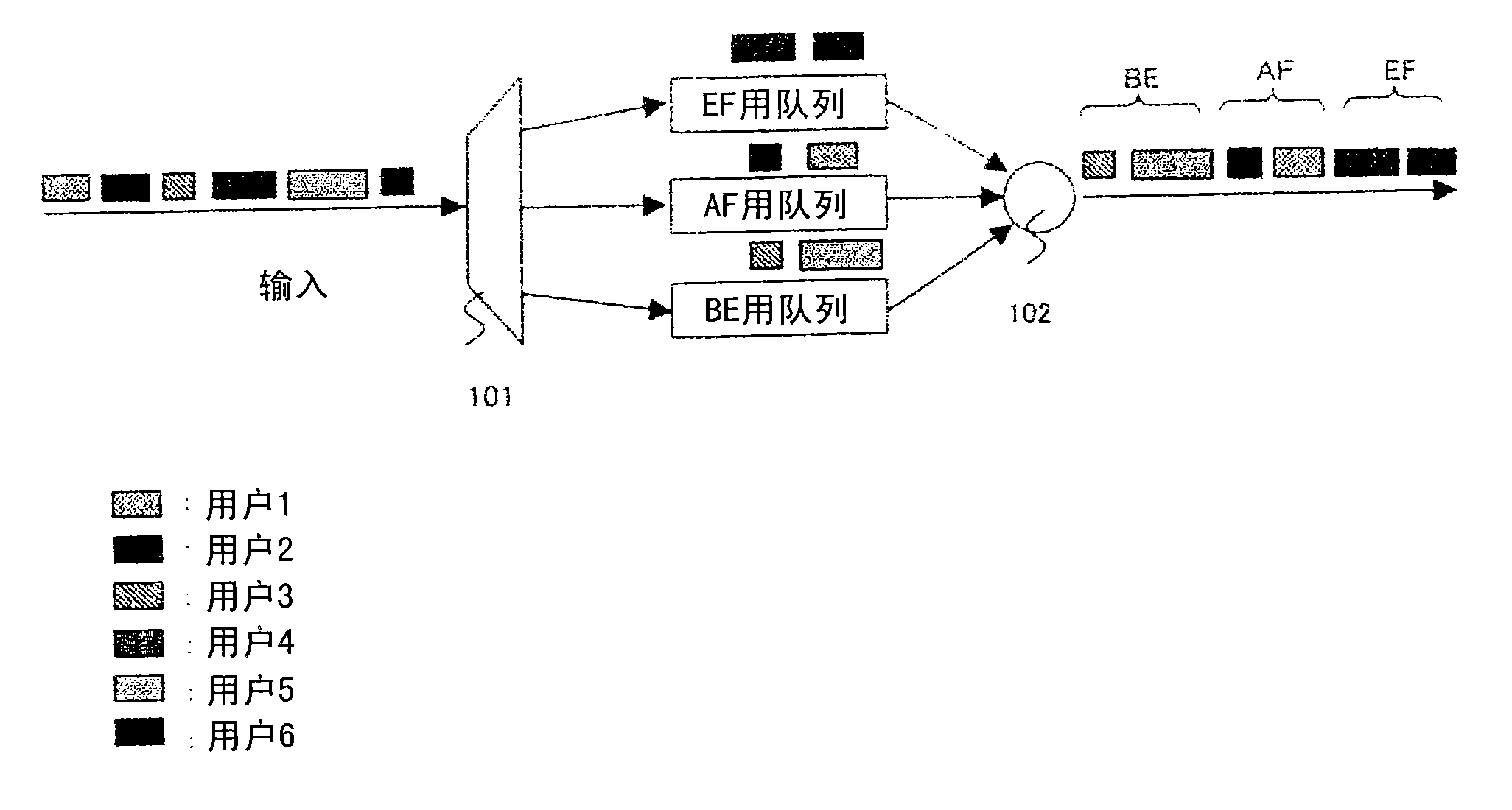
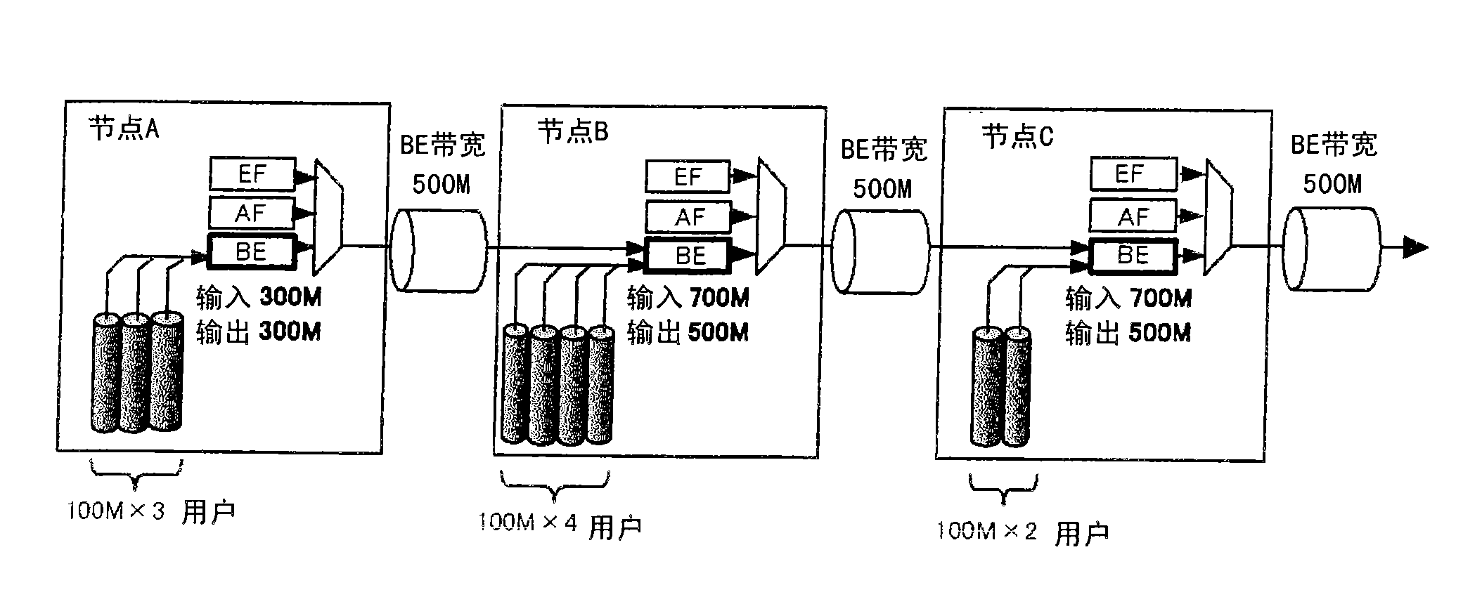
[0028] In the case of BE (Best Effort) traffic, when user signals are efficiently accommodated by using the vacant bandwidth other than the guaranteed bandwidth through the statistical multiplexing effect, and the Diffserv method that performs bandwidth control for each service class is adopted , there is a problem that, since the bandwidth control per user unit is not performed, even for users who have the line service of Best Effort that provides the same service level, the ratio of the used bandwidth that is actually allocated according to the accommodation base varies among users. unfair

Method used


Image

  • Communication system
  • Communication system
  • Communication system

Examples


Embodiment 1

[0046] Figure 4 The basic structure of the network and the bandwidth control device constituted by the bandwidth control device of the present invention is shown in . In this example, if Figure 4 As shown, network 410 is used to connect bandwidth control devices 400-405 in a ring, and user signals are received at a certain site, and user signals are transmitted to another site.

[0047] Such as Figure 4 As shown in the enlarged part 407 of the enlarged figure, the bandwidth control device (referred to as 401 as an example) includes: two NNIs (NNI1, NNI2) (NNI: Network Node Interface) as interfaces connecting nodes; n UNIs (UNI1~UNIn) of the user signal interface (UNI: User Network Interface); can transmit to any interface (NNI1, NNI2, UNI1~UNIn) in each interface (NNI1, NNI2, UNI1~UNIn) The cross-connect section of the cross-connect function of the received signal. This cross-connect unit is based not on circuit switching of continuous data streams such as SDH and SONET...

Embodiment 2

[0080] Figure 11 This is an example of the second block configuration of the priority control unit. Compared with the structure shown in the first embodiment, the method of obtaining the number of THR routes (the number of streams) in this embodiment is different. In this embodiment, the number of routes (number of streams) from NNI is notified from adjacent nodes as storage information, and the number of routes (number of streams) transmitted to UNI is subtracted to calculate the number of THR routes. Generally, the larger the network size, the more THR routes must be managed. In the first embodiment, the network management device collectively manages the THR routes of all the nodes, but according to the second embodiment, only the multiplexing (ADD) and separate (DRP) the difference of several routes (data streams), calculate the number of THR routes from them, and manage the state of THR routes in a decentralized manner for each node, which is more advantageous in terms ...


PUM


Abstract

A communication system with improved fairness of band allotment among the users accommodated by different node. Traffic received by UNI interface and traffic received by NNI interface are stored in separate queues and the respective numbers of paths received by the UNI interface and the NNI interface are measured based on route information. The traffic received by the UNI interface and the traffic received by the NNI interface are distributed based on the measured result.

Description

technical field [0001] The present invention relates to priority control of communication systems. Background technique [0002] In recent years, broadband lines such as the Internet for each home have become popular, and the demand for lines centered on IP traffic has increased, and the diversification of services accommodated therein has also rapidly developed. [0003] Among them, the importance of "QoS (Quality Of Service)" is the idea of ​​requesting to secure network resources and guaranteeing the reservation of secured resources in order to ensure the communication quality required to transfer IP traffic containing various services more and more high. [0004] The so-called QoS control is the control performed to ensure the communication quality required to provide each service received. As the specific parameters of the communication quality, the "rate", "delay time" and "jitter (fluctuation) of the packet are mainly determined. )" and "packet loss" are specified. ...

Claims


Application Information

Patent Timeline
Patent Type & Authority Applications(China)
IPC IPC(8): H04L12/56H04L47/22H04L47/525H04L47/6275
CPCH04L47/58H04L47/6275H04L12/5693H04L47/6215H04L47/60H04L47/623H04L47/6295H04L47/629H04L47/50
Inventor 渥美俊之
Owner HITACHI LTD
Learn More