
Radiating fan casing seat

A heat dissipation fan and vane technology, which is applied to components of pumping devices for elastic fluids, non-variable pumps, pump devices, etc., can solve the problem of wind-cut noise caused by air flow, no centralized air flow structure design, Affect wind pressure and other issues to achieve the effect of increasing wind pressure and air volume

Active Publication Date: 2010-10-27
SUNONWEALTH ELECTRIC MACHINE IND
View PDF0 Cites 0 Cited by
  • Summary
  • Abstract
  • Description
  • Claims
  • Application Information

AI Technical Summary

Problems solved by technology

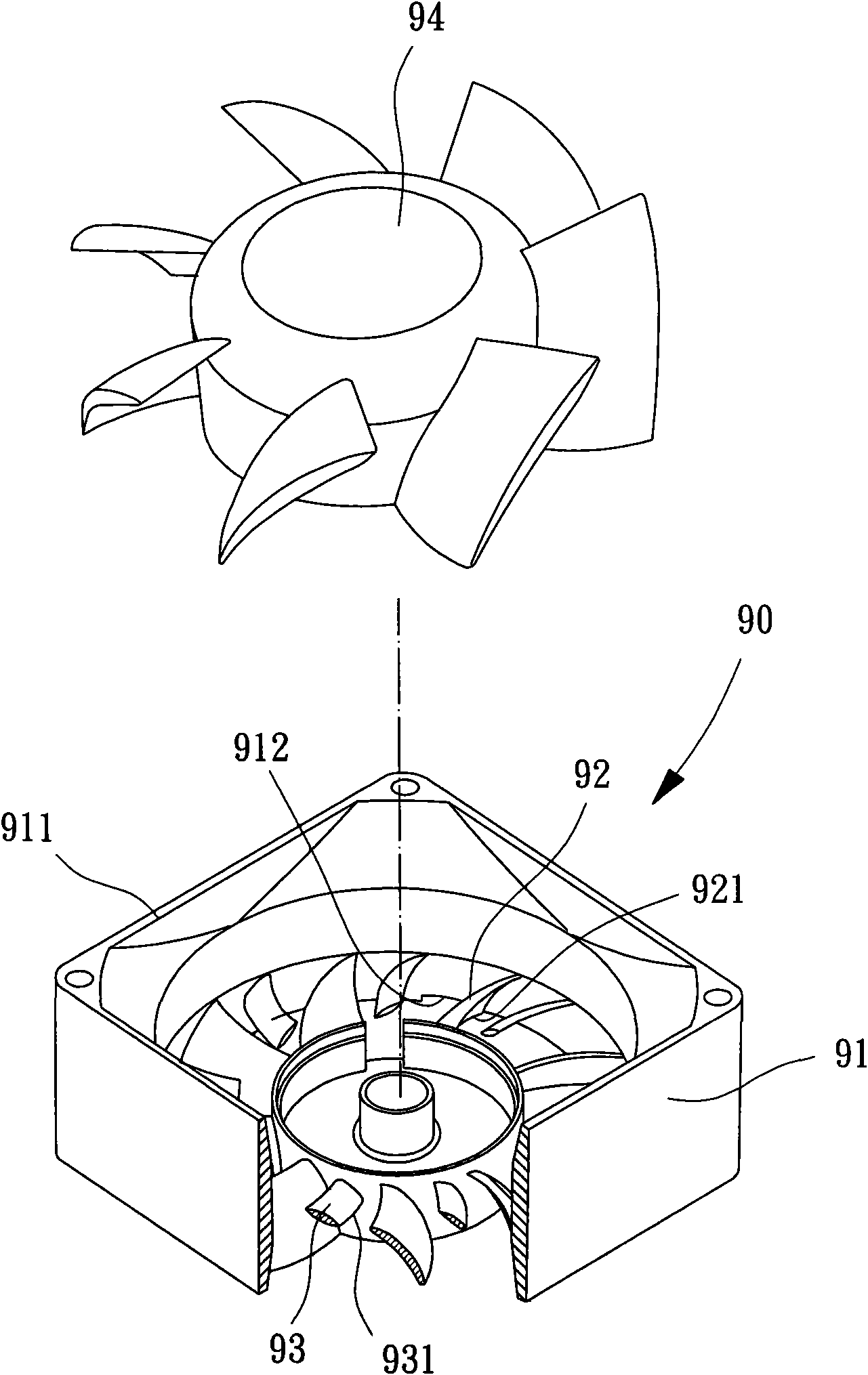
[0006] However, although the second type of existing heat dissipation fan case base 90 utilizes the wing-shaped air guides 93 to achieve the function of reducing noise, it must also form several airfoil guides on the inner edge of the outer frame 91. Part 93, so it is not easy to make and shape, and relatively leads to an increase in the overall manufacturing cost
Furthermore, although the bottom edge 931 of each wing-shaped air guide 93 of the existing cooling fan case base 90 is not aligned with the air outlet 912 of the outer frame 91, the bottom edge 921 of each stationary vane 92 is still It is aligned with the air outlet 912 of the outer frame 91; therefore, the inner side of the outer frame 91 near the air outlet 912 has no structural design for concentrating the air flow; when the rotor blade 94 rotates, the air flow generated If it is not concentrated, it will cause the airflow to spread to different directions immediately after passing through each of the stator blades 92, and also cause the airflow to easily generate wind shear noise between each other, and still affect each of the stator blades 92 is used to strengthen the effect of the wind pressure of this airflow

Method used


Image

  • Radiating fan casing seat
  • Radiating fan casing seat
  • Radiating fan casing seat

Examples


Embodiment Construction

[0031] In order to make the above-mentioned and other objects, features and advantages of the present invention more comprehensible, the preferred embodiments of the present invention are specifically cited below, together with the accompanying drawings, and are described in detail as follows:

[0032] Please refer to Figure 4 and Figure 5 As shown, the heat dissipation fan case base of the present invention at least includes an outer frame 10 , a receiving portion 20 and several vanes 30 .

[0033] The outer frame 10 has an accommodating space 11 inside, and an air inlet 12 and an air outlet 13 are respectively formed at two ends of the accommodating space 11 . Moreover, the accommodating space 11 of the outer frame 10 can form a moving blade area 111 , a stationary blade area 112 and a collecting area 113 in sequence from the air inlet 12 toward the air outlet 13 .

[0034] The receiving portion 20 is disposed in the accommodation space 11 of the outer frame 10, and is m...


PUM


Abstract

The invention provides a radiating fan casing seat, comprising an outer frame, a bearing part and a plurality of fixed blades, wherein, the outer frame is internally equipped with a holding space; an air inlet and an air outlet are respectively formed at two ends of the holding space; the bearing part is arranged in the holding space; and the fixed blades are combined between the outer frame and the bearing part. The holding space of the outer frame sequentially forms a moving blade area, a fixed blade area and a current collecting area from the air inlet towards the air outlet, wherein, the fixed blades are positioned in the fixed blade area; the fixed blades are respectively provided with a first end edge towards the air inlet and a second end edge towards the air outlet; and the current collecting area is positioned between the second end edge and the air outlet. In the invention, the current collecting area can be effectively adopted to concentrate and guide air current so as to achieve the efficacies of reduced noise, increased wind pressure, saved power consumption and the like.

Description

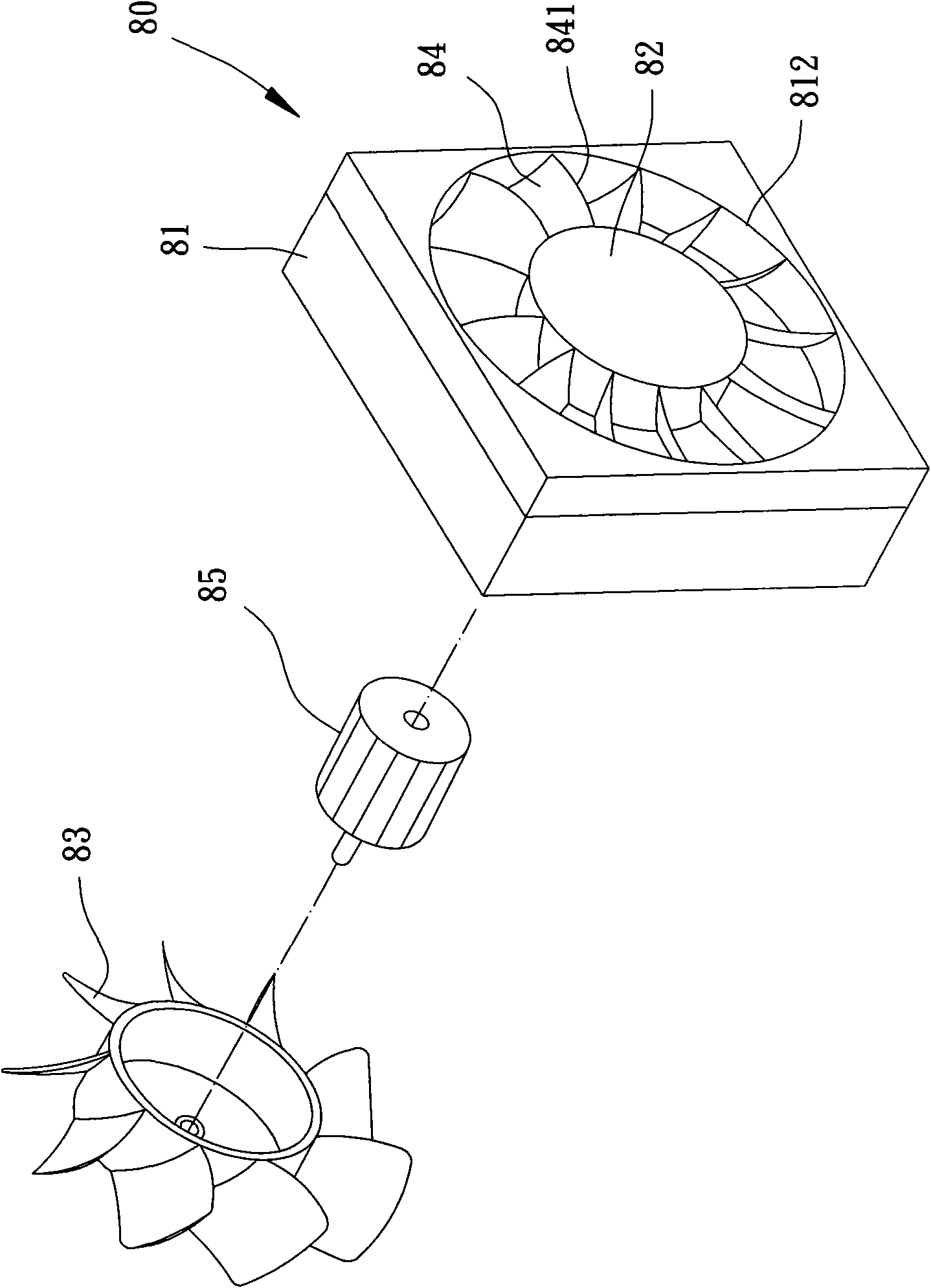
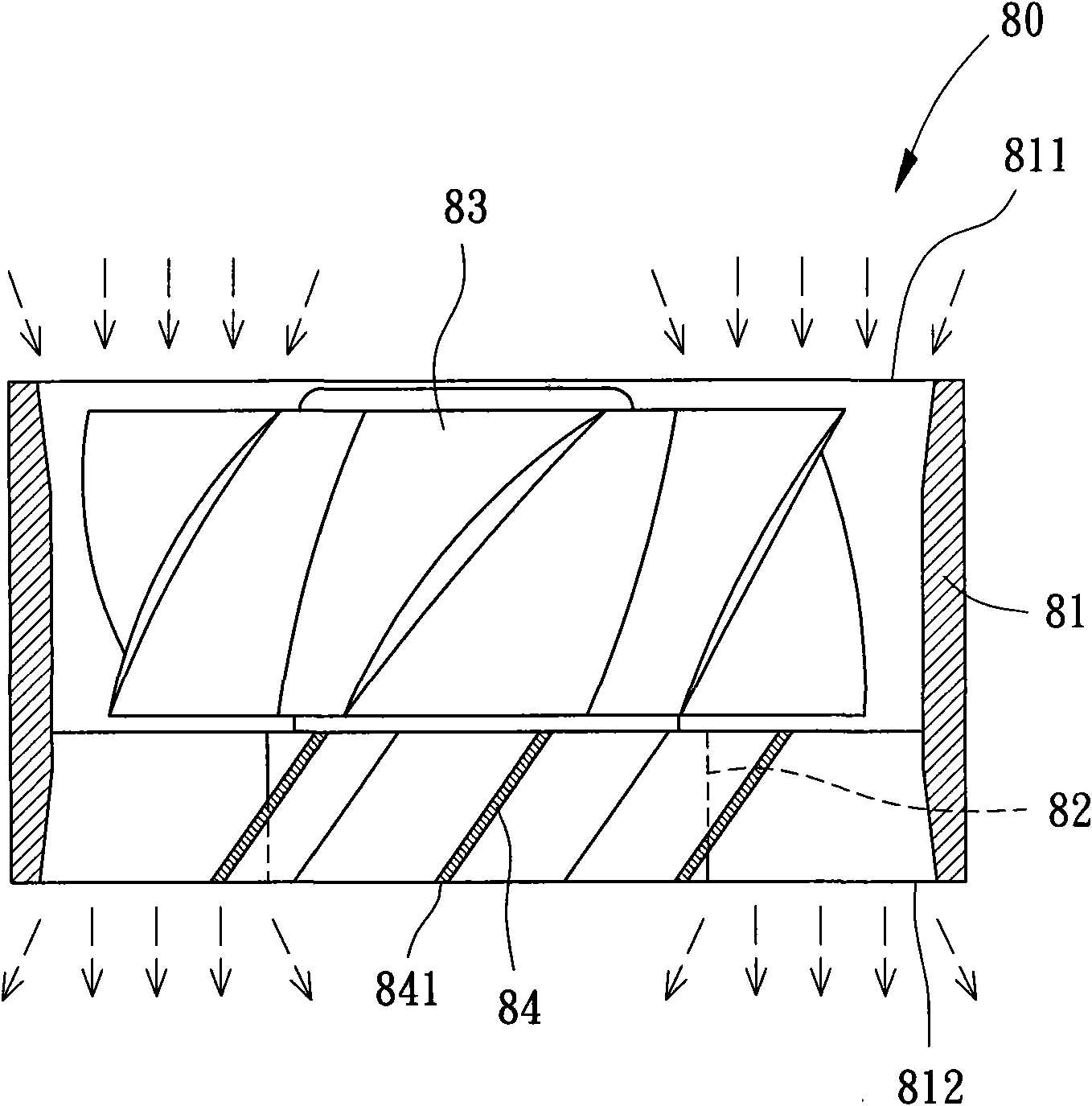
technical field [0001] The present invention relates to a fan frame structure, in particular to a heat dissipation fan case seat with stator vane design. Background technique [0002] At present, the common heat dissipation fan housings on the market usually have a vane structure, so that the design of the vane can be used to achieve the effect of pressurization and flow diversion. Such as China Taiwan Announcement No. 488497 "fan pressurization deflector device" new patent, discloses the first kind of existing cooling fan case seat with stationary blade. Please refer to figure 1 As shown, the heat dissipation fan case seat 80 has an outer frame 81, and the inner side of the outer frame 81 has a receiving portion 82, and the receiving portion 82 can be combined with a moving blade 83, and the rotating blade 83 is controlled by a driving device 85. , and the bearing part 82 is connected with a flow guiding device composed of several stationary vanes 84, and each of the stat...

Claims


Application Information

Patent Timeline
Patent Type & Authority Applications(China)
IPC IPC(8): F04D25/08F04D29/52F04D29/38
Inventor 洪银树李明聪
Owner SUNONWEALTH ELECTRIC MACHINE IND
Learn More