
Vertical reciprocating grate

A reciprocating grate, vertical technology, applied in the field of boiler grate, to achieve the effect of easy ignition, good combustion and low ventilation resistance

Inactive Publication Date: 2010-10-13
黑龙江双锅锅炉股份有限公司
View PDF0 Cites 9 Cited by
  • Summary
  • Abstract
  • Description
  • Claims
  • Application Information

AI Technical Summary

Problems solved by technology

[0003] The technical problem to be solved by the present invention is the reciprocating transmission fire grate used on the existing layer combustion furnace. The working surface of the fire grate is horizontal or flat with a slight slope angle. Layered distribution, the operation of the fuel is only realized by the thrust generated by the reciprocating motion of the movable grate relative to the fixed grate, which not only prolongs the ignition time of the fuel, but also tends to cause retention, coking, large ventilation resistance, and reduces the combustion of the boiler. Insufficient effect or failure to burn properly

Method used


Image

  • Vertical reciprocating grate
  • Vertical reciprocating grate
  • Vertical reciprocating grate

Examples


Embodiment Construction

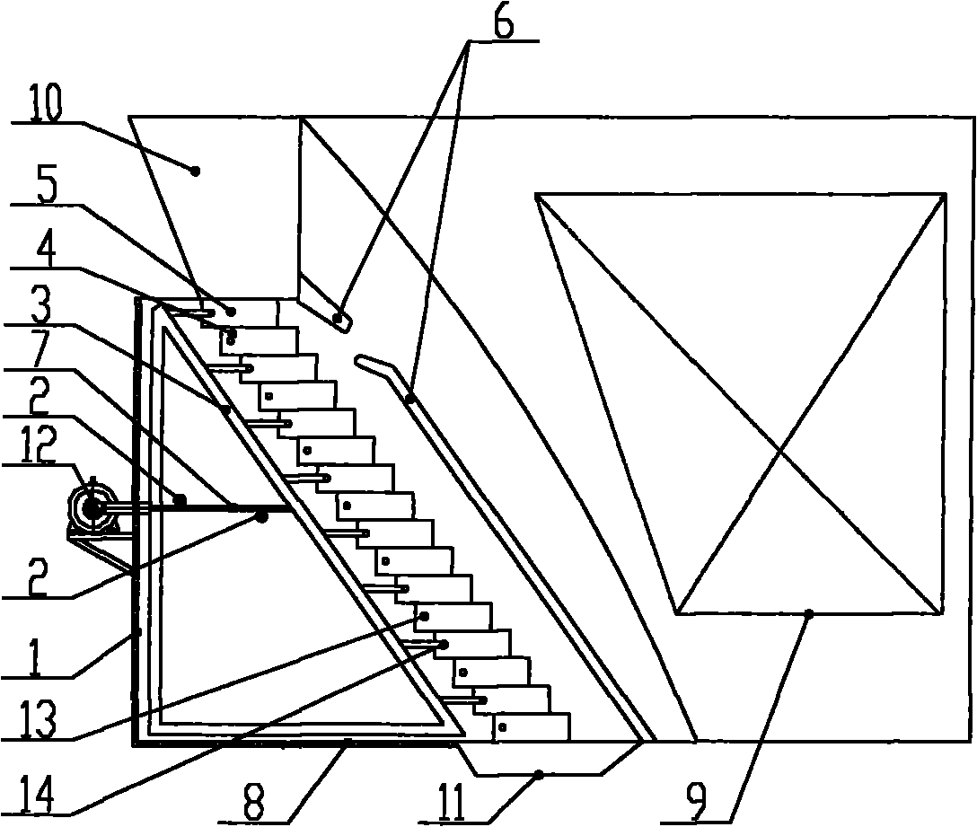
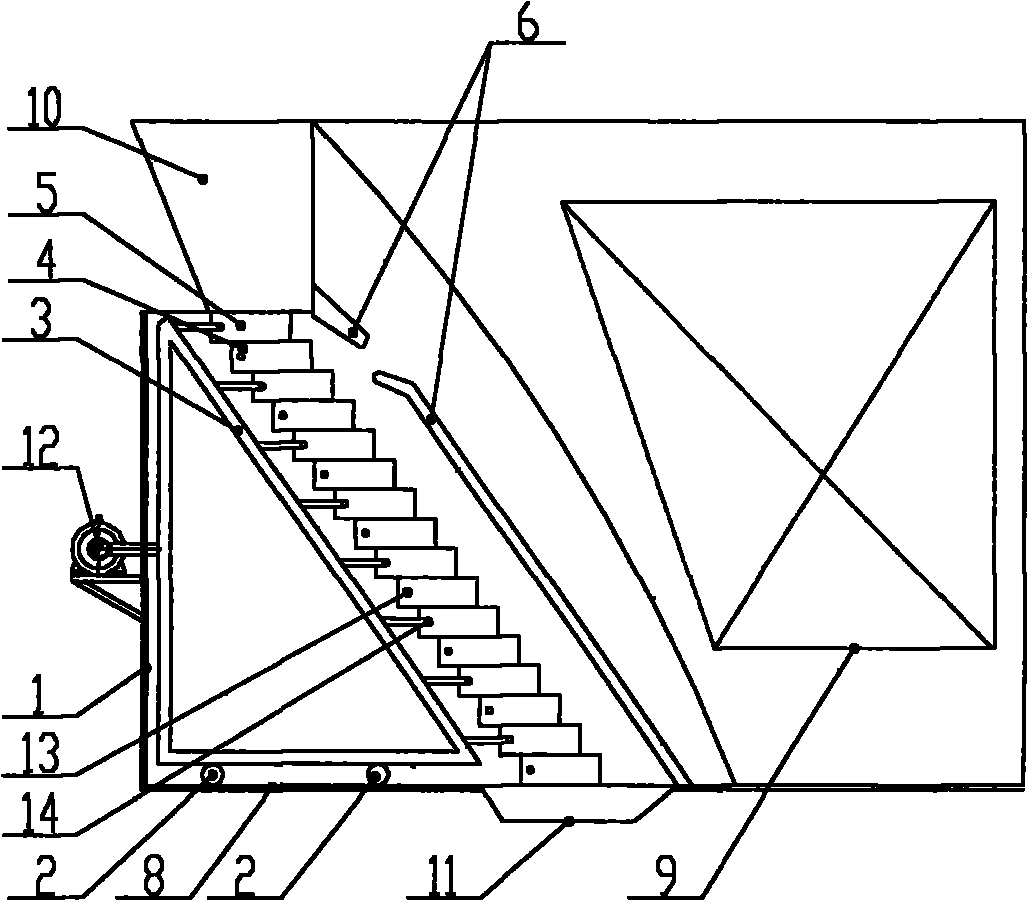
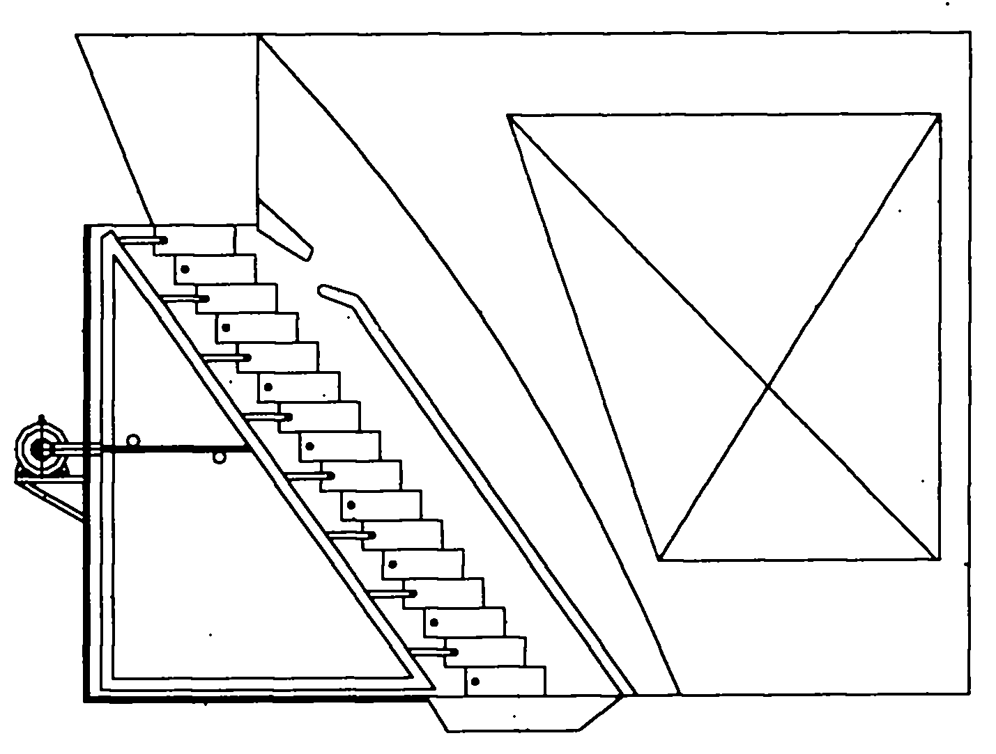
[0008] Provide preferred embodiment of the present invention below in conjunction with accompanying drawing: By figure 1 In the given embodiment, the vertical reciprocating grate is fixed on the fixed grate bracket 1, the movable grate bracket installation roller 2 on the left and right side walls of the fixed grate bracket 1, and the movable grate bracket 3. The fixed grate support 1 is composed of the fixed grate 4 on the grate installation beam, the movable grate 5 fixed on the movable grate support 3 and the reflective arch 6 on the grate installation beam, the fixed grate support 1 and the movable grate support 3 It is a vertical frame with a front slope angle greater than 35 degrees. The grate installation beams 13.14 on the fixed grate support 1 and the movable grate support 3 are distributed on the front slope, and the fixed grate 4 and the movable grate The working surface of the reciprocating fire grate formed by the strips 5 is stepped, and the reflective arch 6 is ...


PUM


Abstract

The invention relates to a vertical reciprocating grate, aiming at solving the technical problems that when the grate is transmitted back and forth, the working surface of the grate is in the form of a horizontal flat slope or a flat slope with a small slope angle; accumulated continuous layered distribution is formed on the working face of the grate during the fuel operation period, and fuel operation is realized only by the thrust generated by reciprocating motion of mobile grate sheets relative to fixed grate sheets, thus leading long fuel ignition time, easy generation of lag and coking, and large ventilation resistance, and reducing the combustion effect of a boiler. The technical scheme of the invention is as follows: the vertical reciprocating grate comprises a fixed grate sheet support, a mobile grate sheet support, fixed grate sheets, mobile grate sheets and a reflecting arch, wherein, the fixed grate sheet support and the mobile grate sheet support are vertical support bodies the front sides of which are inclined, the working surface of the reciprocating grate composed of the fixed grate sheets and the mobile grate sheets is in a stepped shape, and the reflecting arch is of a vertical structure and correspondingly matched with the stepped working surface.

Description

technical field [0001] The invention relates to a boiler grate, in particular to a vertical reciprocating grate. Background technique [0002] At present, for the reciprocating transmission grate used on the layer combustion furnace, the working surface of the grate is horizontal or flat with a small slope angle (15-20 degrees), and a continuous layer of accumulation is formed on the working surface of the grate during fuel operation. distribution, the operation of the fuel is realized only by the thrust generated by the reciprocating motion of the movable grate relative to the fixed grate, because the front of the upper fuel layer that does not touch the grate forms resistance to the rear of the upper fuel, making it contact with the furnace The lower layer of the fuel is not easy to drive the upper layer of the fuel to run. The fuel not only prolongs the ignition time, but also tends to be retained, which leads to the overall coking of the upper layer of the fuel and the r...

Claims


Application Information

Patent Timeline
IPC IPC(8): F23H11/12F23H11/18
Inventor 马成果佟海川谭伟东司艳华宋金勇王宝华
Owner 黑龙江双锅锅炉股份有限公司
Learn More