
Anti-rotation connecting structure and lamp using the same

A connection structure and anti-rotation technology, which is applied to the components of lighting devices, lighting auxiliary devices, lighting and heating equipment, etc., can solve the problems of poor product reliability, random changes in angles, and unfavorable accurate adjustment of product main body angles, so as to achieve reliable Good, precisely adjusted results

Inactive Publication Date: 2010-10-13
OCEANS KING LIGHTING SCI&TECH CO LTD +1
View PDF4 Cites 18 Cited by
  • Summary
  • Abstract
  • Description
  • Claims
  • Application Information

AI Technical Summary

Problems solved by technology

[0002] In the prior art, in some professional product fields, such as lighting, security and other product fields, a bolt is used between the product body and the base or mounting surface to directly connect the product to the base or mounting surface, so as to adjust the product during installation. The angle of the main body is to make the main body of the lamps and security products work in the set orientation, but when the bolts are slightly loosened, the main body of the lamps and security products will rotate around the bolt, resulting in the angle of the main body of the product Random changes are not conducive to the normal use of the product, and the reliability of the product is poor; in addition, when the angle of the main body of the lamp or security product needs to be adjusted, the user first loosens the bolt, then adjusts the angle of the main body of the product, and finally tightens the bolt. However, in this structure in the prior art, when the bolt is tightened, due to the friction between the bolt and the product body, the product body and the bolt will rotate synchronously, which is not conducive to the precise adjustment of the angle of the product body

Method used


Image

  • Anti-rotation connecting structure and lamp using the same
  • Anti-rotation connecting structure and lamp using the same
  • Anti-rotation connecting structure and lamp using the same

Examples


Embodiment Construction

[0021] In order to make the object, technical solution and advantages of the present invention clearer, the present invention will be further described in detail below in conjunction with the accompanying drawings and embodiments. It should be understood that the specific embodiments described here are only used to explain the present invention, not to limit the present invention.

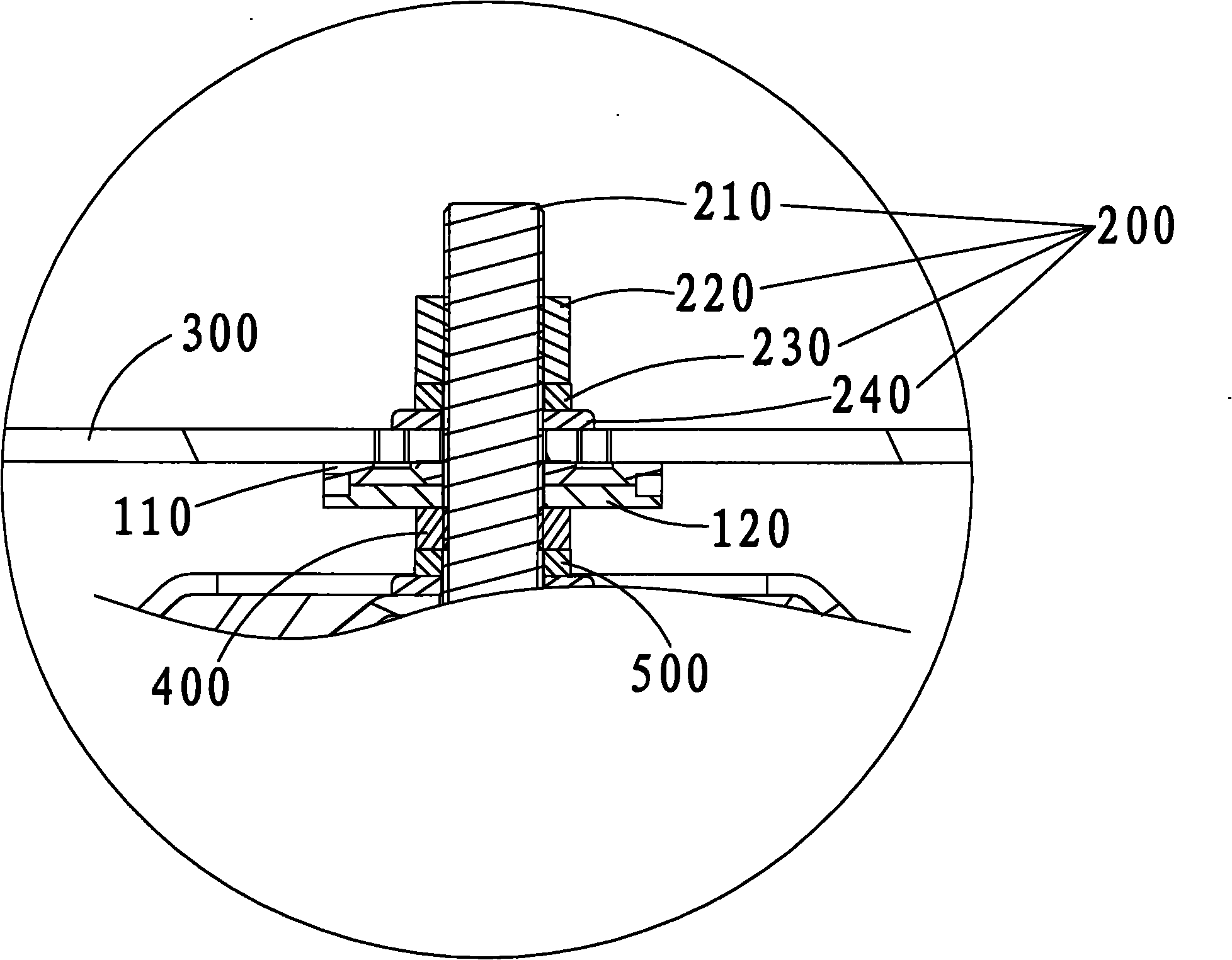
[0022] Such as Figure 1 ~ Figure 3 As shown, the anti-rotation connection structure provided by the embodiment of the present invention can be used on products such as lamps 600 and security products that need to adjust the rotation angle of the product. In this embodiment, it is fixedly connected to the lamp 600. The anti-rotation The connecting structure includes a first adjusting disc 110, a second adjusting disc 120, and a pressing assembly 200 that can press the first adjusting disc 110 and the second adjusting disc 120 up and down, and the pressing assembly 200 is passed through the The fir...


PUM


Abstract

The invention is applicable to the field of connecting structures, and discloses an anti-rotation connecting structure and a lamp using the structure. The anti-rotation connecting structure comprises a first regulating disk, a second regulating disk and a compacting assembly, wherein the compacting assembly can be used for vertically bonding and compacting or loosing the first regulating disk and the second regulating disk, the compacting assembly penetrates through the first regulating disk and the second regulating disk, and fluctuant surfaces which are mutually engaged along a circumferential direction are arranged on the bonded end surfaces of the first regulating disk and the second regulating disk; and the lamp is provided with the anti-rotation connecting structure. In the anti-rotation connecting structure and the lamp using the structure provided by the invention, the fluctuant surfaces which can be mutually engaged along the circumferential direction are arranged on the mutually bonded surfaces of the first regulating disk and the second regulating disk, thereby the random angle rotation of products such as the lamp and the like can be prevented, the rotation angles of the products such as the lamp and the like can be accurately adjusted, and the reliability is good.

Description

technical field [0001] The invention belongs to the field of connection structures, in particular to an anti-rotation connection structure and a lamp using the structure. Background technique [0002] In the prior art, in some professional product fields, such as lighting, security and other product fields, a bolt is used between the product body and the base or mounting surface to directly connect the product to the base or mounting surface, so as to adjust the product during installation. The angle of the main body is to make the main body of the lamps and security products work in the set orientation, but when the bolts are slightly loosened, the main body of the lamps and security products will rotate around the bolt, resulting in the angle of the main body of the product Random changes are not conducive to the normal use of the product, and the reliability of the product is poor; in addition, when the angle of the main body of the lamp or security product needs to be ad...

Claims


Application Information

Patent Timeline
Patent Type & Authority Applications(China)
IPC IPC(8): F21V21/10
Inventor 周明杰蒋莉
Owner OCEANS KING LIGHTING SCI&TECH CO LTD
Learn More