Reverse boring cutter
A technology of back-boring cutter and cutter body, which is applied in the direction of boring head, tool holder, etc., can solve the problems of affecting the efficiency of processing, cumbersome processing preparation work, and affecting the processing accuracy of inner wall step holes, so as to improve processing efficiency and space utilization Efficiency increase, anti-rotation effect and anti-rotation torque optimization effect
- Summary
- Abstract
- Description
- Claims
- Application Information
AI Technical Summary
Problems solved by technology
Method used
Image
Examples
Embodiment 1
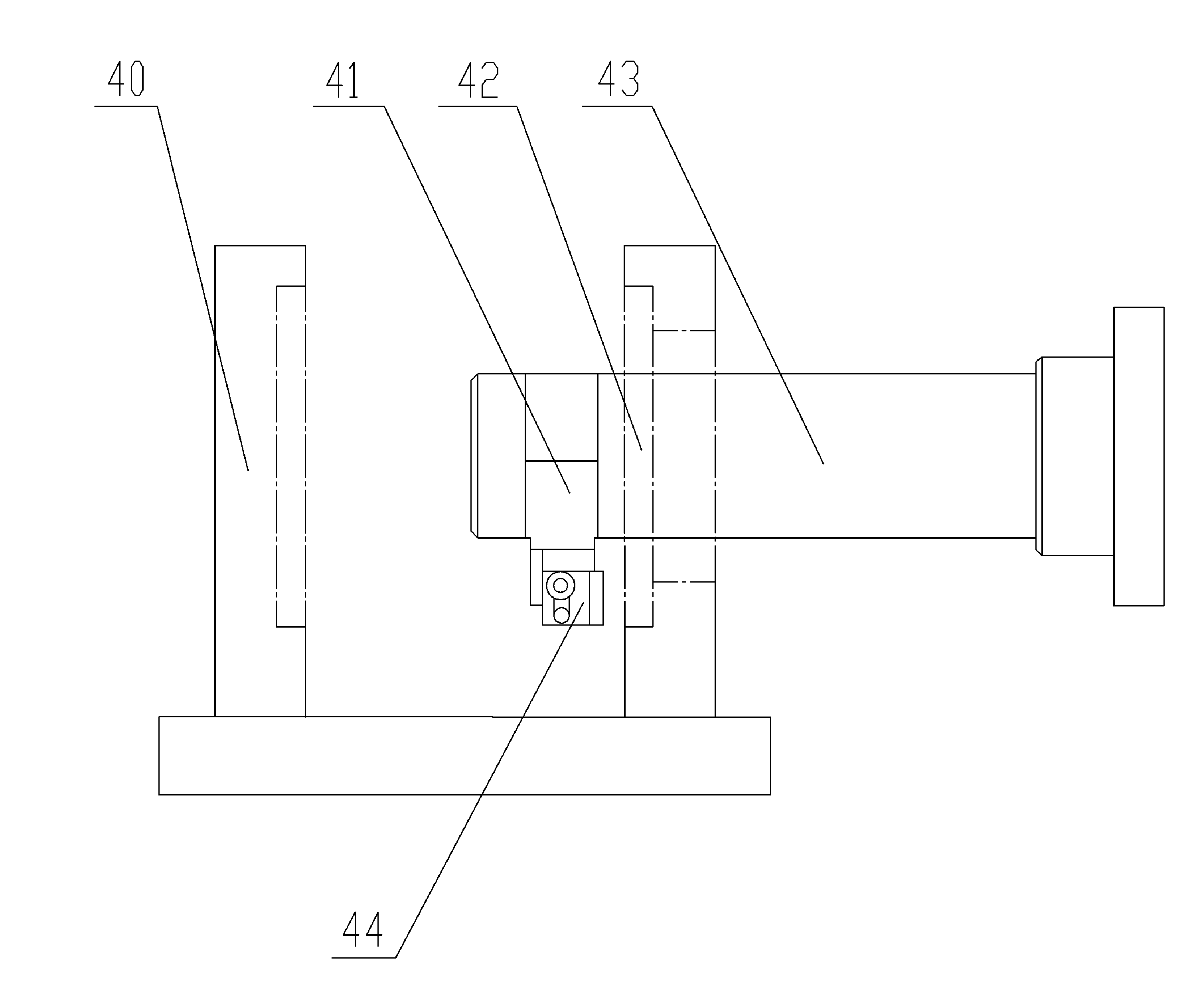
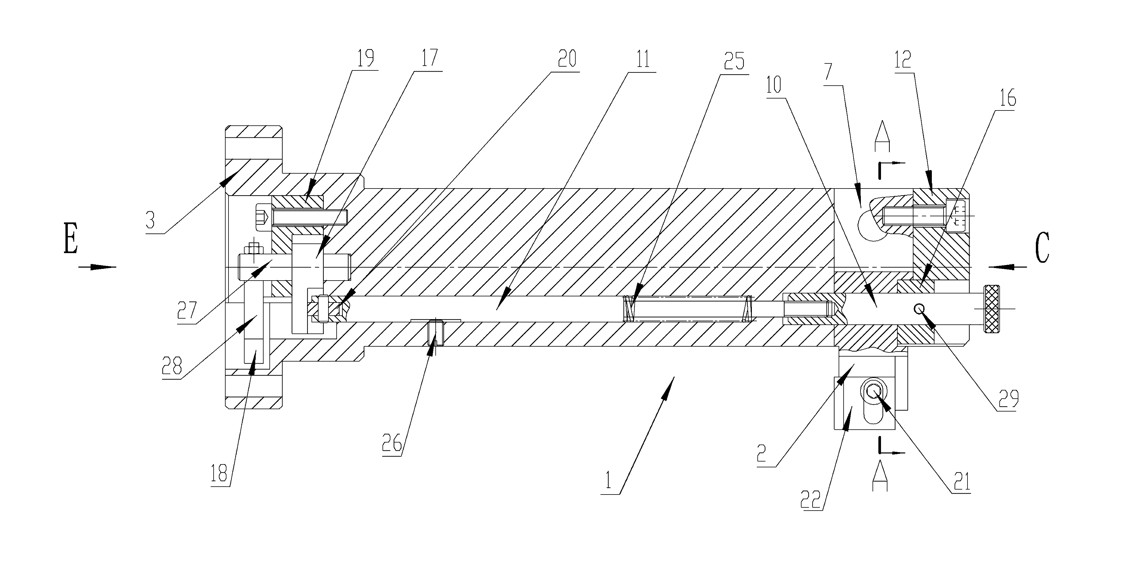
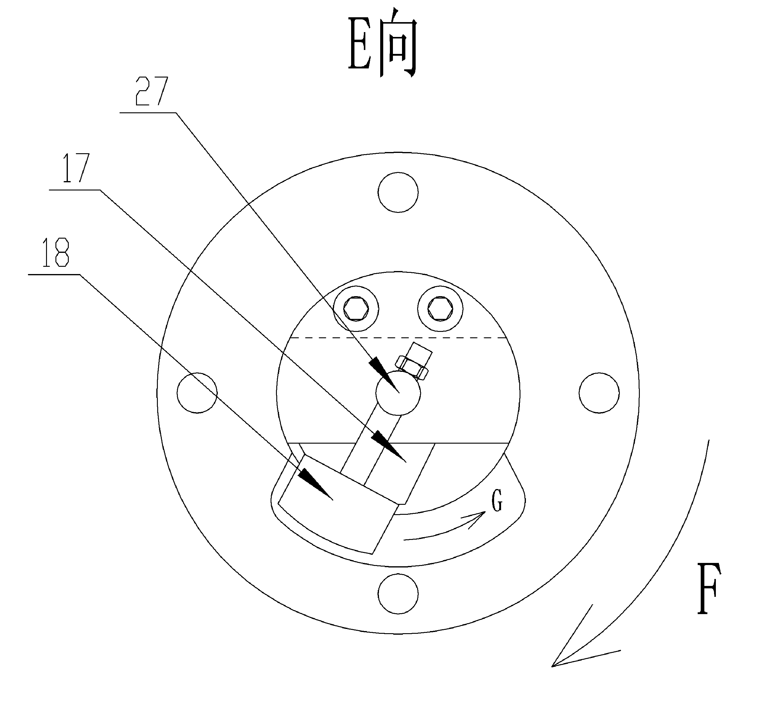
[0033] The back boring tool of the present invention is as figure 2 , 3 , Shown in 4, including the cutter bar 1 and the cutter body 2, the cutter body 2 is arranged on the processing side of the cutter bar 1. Knife bar 1 is made of knife bar body 3 and the end block 12 that is fixedly connected at the front end of knife bar body 3, and knife bar body is as Figure 6 , 7 As shown, end blocks such as Figure 8 , 9 As shown, the rear end of the tool body 3 is provided with a flange 5 for connecting with the motor and a cavity 6 for accommodating the inertial drive mechanism, and a gap 4 is opened at the front end, and the gap 4 is formed together with the inner wall of the end block for accommodating The slit 7 of the cutter body 2; the lower side of the cutter body 3 is provided with a long hole 8 connecting the cavity 6 and the gap 4, and the end block 12 is provided with a shaft hole 9 corresponding to the long hole 8. Slotted hole 8 front and back respectively is inser...
Embodiment 2
[0040] The structure of the anti-boring tool of this embodiment is basically the same as that of Embodiment 1, the difference is that this embodiment uses a bidirectional drive cam to replace the unidirectional drive cam in Embodiment 1—the fan-shaped cam 18. The so-called bidirectional drive cam can drive telescopic The cam of the two-way (telescopic) movement of the rod, the two-way driving cam of the present embodiment adopts the following Figure 14 As shown in the cylindrical cam 30, the cylindrical surface of the cylindrical cam 30 is provided with a curved groove 32, and the rear end of the telescopic rod 11 is provided with a crank arm 31 that matches the curved groove 32, and the end of the crank arm 31 is provided with a roller 33 .
[0041] When the back-boring tool of this embodiment is working, the rotation of the cylindrical cam drives the reciprocating movement of the telescopic rod, and no return spring is needed to provide the reset power of the telescopic rod...
PUM
 Abstract
Description
Claims
Application Information
 - R&D Engineer
- R&D Manager
- IP Professional
- Industry Leading Data Capabilities
- Powerful AI technology
- Patent DNA Extraction
Browse by: Latest US Patents, China's latest patents, Technical Efficacy Thesaurus, Application Domain, Technology Topic, Popular Technical Reports.
© 2024 PatSnap. All rights reserved.Legal|Privacy policy|Modern Slavery Act Transparency Statement|Sitemap|About US| Contact US: help@patsnap.com


