Blade arrangement mode of compressor blade row for enhancing air load and stability
An aerodynamic load and stability technology, which is applied to components of pumping devices for elastic fluids, machines/engines, liquid fuel engines, etc., can solve the difficulty of increasing the aerodynamic load at small angles of attack on the blade cascade and improve the effect of aerodynamic stability To achieve the effect of improving the aerodynamic stability of the cascade, improving the aerodynamic stability, and increasing the aerodynamic load
- Summary
- Abstract
- Description
- Claims
- Application Information
AI Technical Summary
Problems solved by technology
Method used
Image
Examples
Embodiment 1
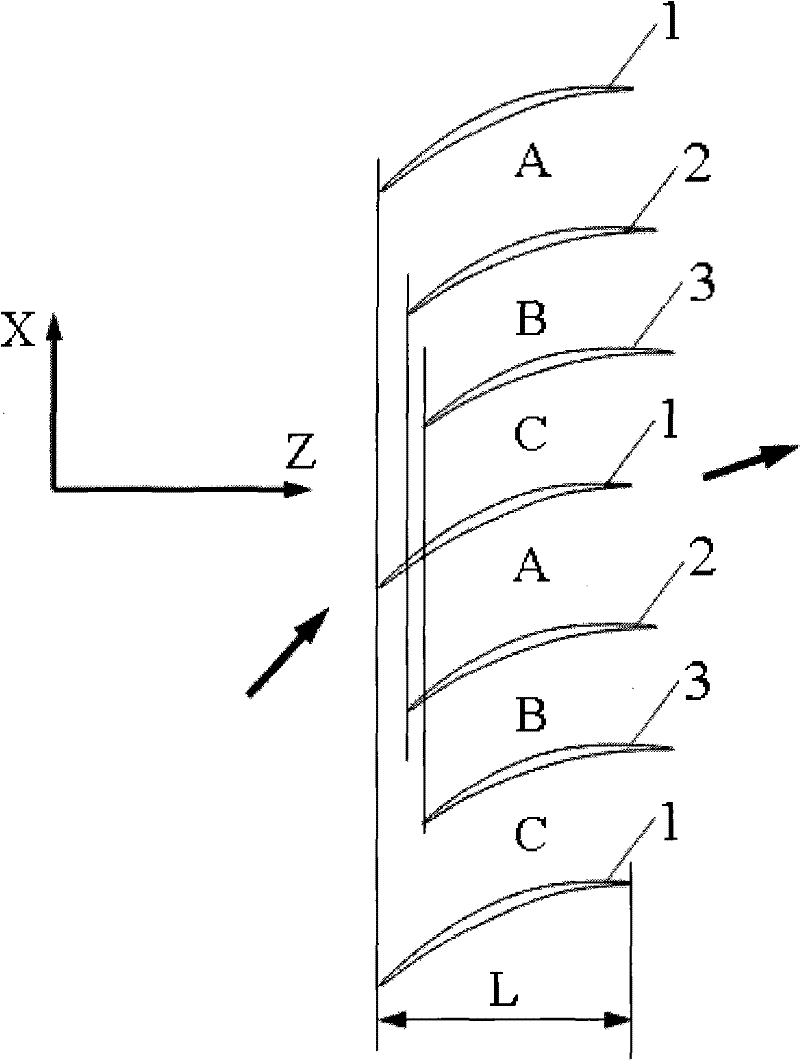
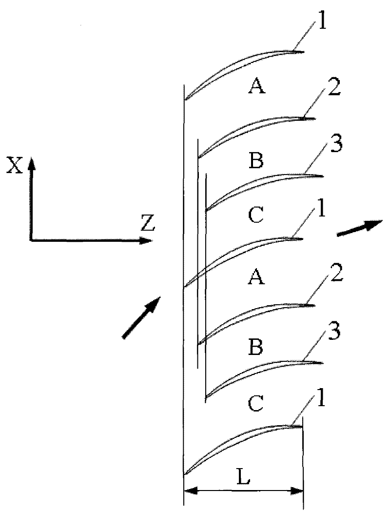
[0024]The arrangement of the cascade in this embodiment is as follows: the front edges of the same row of blades along the tangential direction of the cascade, that is, the X direction, are arranged differently in the front and rear of the cascade axial direction, that is, the Z direction. In the same blade set, taking the axial position of the leading edge of the first blade as the axial positioning reference, the second adjacent blade 2 is located on the side of the blade pot surface of the first blade 1, and its leading edge position Relative to the positioning reference, move back a certain distance along the axial direction of the cascade, and the moved distance is 11% of the axial chord length L of the first blade 1; the third blade 3 adjacent to the second blade 2 is located at On the side of the surface of the blade pot of the second blade 2, the axial position of its leading edge moves back a certain distance relative to the leading edge of the second blade 2 along the...
Embodiment 2
[0028] The arrangement of the cascade in this embodiment is as follows: the front edges of the same row of blades along the tangential direction of the cascade, that is, the X direction, are arranged differently in the front and rear of the cascade axial direction, that is, the Z direction. In the same blade set, taking the axial position of the leading edge of the first blade as the axial positioning reference, the second adjacent blade 2 is located on the side of the blade pot surface of the first blade 1, and its leading edge position Relative to the positioning reference, move back a certain distance along the axial direction of the cascade, and the moved distance is 7% of the axial chord length L of the first blade 1; the third blade 3 adjacent to the second blade 2 is located at On the side of the surface of the blade pot of the second blade 2, the axial position of its leading edge moves back a certain distance relative to the leading edge of the second blade 2 along the...
Embodiment 3
[0030] The arrangement of the cascade in this embodiment is as follows: the front edges of the same row of blades along the tangential direction of the cascade, that is, the X direction, are arranged differently in the front and rear of the cascade axial direction, that is, the Z direction. In the same blade set, taking the axial position of the leading edge of the first blade as the axial positioning reference, the second adjacent blade 2 is located on the side of the blade pot surface of the first blade 1, and its leading edge position Relative to the positioning reference, move back a certain distance along the axial direction of the cascade, and the moved distance is 15% of the axial chord length L of the first blade 1; the third blade 3 adjacent to the second blade 2 is located at On the side of the surface of the blade pot of the second blade 2, the axial position of its leading edge moves back a certain distance relative to the leading edge of the second blade 2 along th...
PUM
 Abstract
Description
Claims
Application Information
 - R&D
- Intellectual Property
- Life Sciences
- Materials
- Tech Scout
- Unparalleled Data Quality
- Higher Quality Content
- 60% Fewer Hallucinations
Browse by: Latest US Patents, China's latest patents, Technical Efficacy Thesaurus, Application Domain, Technology Topic, Popular Technical Reports.
© 2025 PatSnap. All rights reserved.Legal|Privacy policy|Modern Slavery Act Transparency Statement|Sitemap|About US| Contact US: help@patsnap.com


