
Switch power supply and method for adjusting output current thereof

A switching power supply, discharge current technology, applied in the direction of output power conversion device, adjustment of electrical variables, control/regulation system, etc., can solve the problems of power system efficiency decline, cost increase, circuit complexity, etc. Effect

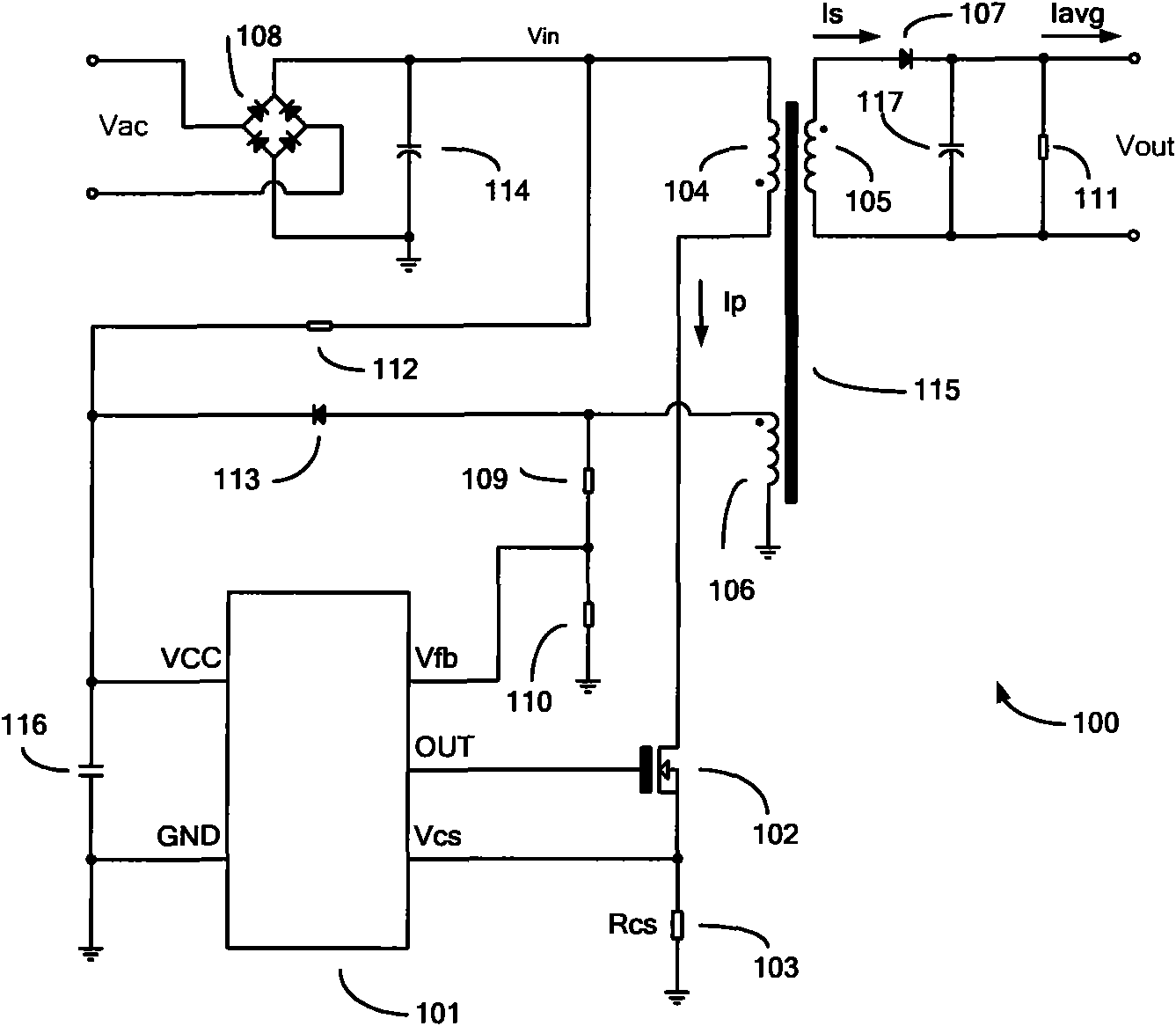
Active Publication Date: 2010-09-22
SHANGHAI LUMIXESS TECH
View PDF4 Cites 34 Cited by
  • Summary
  • Abstract
  • Description
  • Claims
  • Application Information

AI Technical Summary

Problems solved by technology

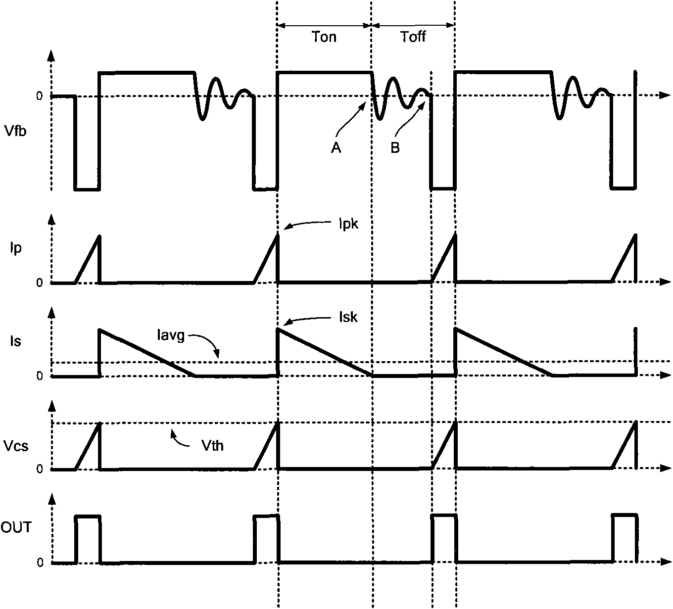
The disadvantage of this technology is: after the internal circuit of the PFM controller 101 is determined, the ratio of the fixed on-time Ton to the off-time Toff makes the generated output current a constant value, which cannot be adjusted according to actual needs.
The disadvantages of this technology are: the output current must be sampled and the feedback is isolated by the optocoupler, which leads to complex circuits and increased costs; the sampling resistance of the output current leads to a decrease in the efficiency of the power system; the signal-to-noise ratio of the output current sampling signal is low at low current time degradation, resulting in poor control accuracy when the output current is small

Method used


Image

  • Switch power supply and method for adjusting output current thereof
  • Switch power supply and method for adjusting output current thereof
  • Switch power supply and method for adjusting output current thereof

Examples


Embodiment Construction

[0061] In order to make the above objects, features and advantages of the present invention more obvious and comprehensible, specific implementations of the present invention will be described in detail below in conjunction with the accompanying drawings and embodiments.

[0062] In the switching power supply of the prior art, since its circuit structure is fixed, the ratio of the turn-on time to the turn-off time of the secondary coil is a fixed value. According to the formula (1), the average value of the output current is also a fixed value, which cannot It is adjusted according to the needs of actual applications, and the flexibility is low. Although the optocoupler isolation feedback structure can adjust the output current, its circuit is complex and difficult to integrate, and the control accuracy is poor when the output current is small.

[0063] The switching power supply in the embodiment of the present invention includes: a transformer, a pulse frequency modulation c...


PUM


Abstract

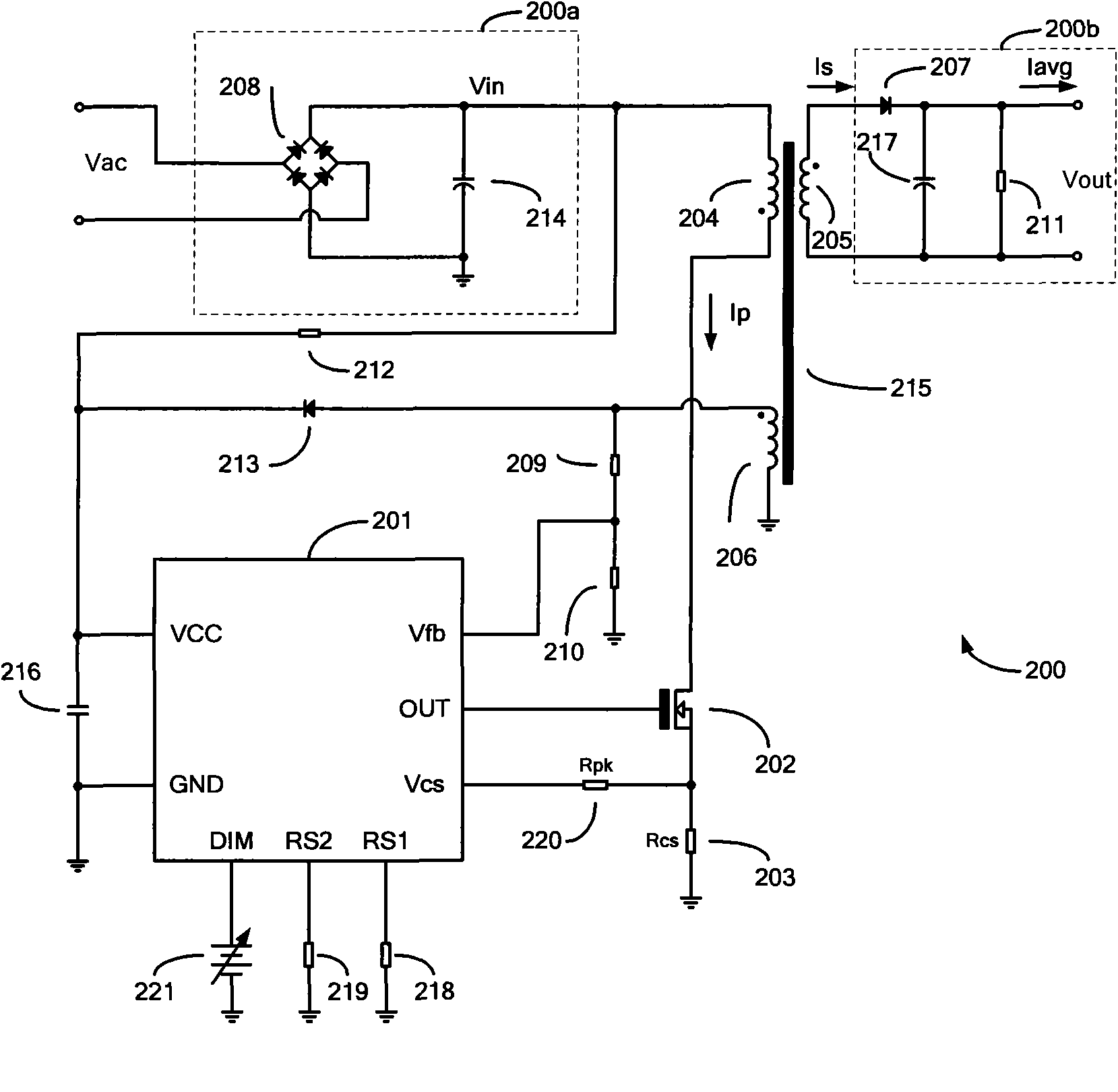
The invention relates to a switch power supply and a method for adjusting output current thereof. The switch power supply comprises a transformer, a pulse frequency modulation controller and a switch transistor; wherein the pulse frequency modulation controller inputs a feedback voltage and a sampling voltage, the feedback voltage is associated with the voltage output by the assistant coil, the sampling voltage is associated with the voltage of a second terminal of the switch transistor, the pulse frequency modulation controller also inputs a control signal, the pulse frequency modulation controller generates the driving voltage according to the feedback voltage, the sampling voltage and the control signal, so as to control the switch transistor to switch on or off of the primary coil, thus adjusting the on time and off time of the secondary coil. The invention improves output current regulating flexibility ratio of switch power supply.

Description

technical field [0001] The invention relates to the field of power supplies, in particular to a switching power supply and a method for adjusting its output current. Background technique [0002] Switching power supplies are widely used because they can generate stable output voltage and have high conversion efficiency. The switching power supply is mainly composed of a pulse frequency modulation (PFM, Pulse Frequency Modulation) controller and a power transistor, and a stable output voltage is generated by controlling the power transistor to be turned on and off. [0003] see figure 1 , which is a typical constant current output flyback switching power supply in the prior art. [0004] The switching power supply 100 mainly includes a PFM controller 101 , a power transistor 102 , a sampling resistor 103 , secondary coil current zero-crossing detection resistors 109 and 110 and a transformer 115 . Wherein, the transformer 115 includes a primary coil 104 , a secondary coil ...

Claims


Application Information

Patent Timeline
IPC IPC(8): H02M3/335
CPCH02M3/33523
Inventor 陈忠
Owner SHANGHAI LUMIXESS TECH
Learn More