
Electrical junction box

A technology of electrical junction box, attachment, applied in the direction of conductive connection, circuit, connection, etc., which can solve the problems of increased production cost, increased number of parts, impossibility to prevent water, etc.

Inactive Publication Date: 2010-09-22
SUMITOMO WIRING SYST LTD
View PDF6 Cites 4 Cited by
  • Summary
  • Abstract
  • Description
  • Claims
  • Application Information

AI Technical Summary

Problems solved by technology

[0005] However, if this large waterproof cover is mounted on the electrical junction box, it will be impossible to avoid problems such as an increase in the number of parts, an increase in production cost, and an increase in assembly steps
In addition, since the large waterproof cover requires a large space to install the electric junction box in the motor vehicle, it will be difficult to adopt such a waterproof cover in practice.
[0006] In addition, even if the waterproof cover covers the entire upper portion of the electrical junction box, it is impossible to prevent water such as rainwater from flowing on the body panel to reach the electrical junction box.
In other words, even if the waterproof cover can prevent water from falling directly on the electrical junction box, since the electrical junction box is fixed to the body panel, it is impossible to prevent rainwater flowing on the vehicle body from flowing to a fixed part such as a bracket while reaching the electrical junction box

Method used


Image

  • Electrical junction box
  • Electrical junction box
  • Electrical junction box

Examples


Embodiment Construction

[0042] The configuration of the present invention for solving the above-mentioned problems will be described below. It should be noted that constituent elements employed in the following configurations can be freely combined with each other as much as possible.

[0043] In order to explain the present invention in more detail, an embodiment of an electrical junction box according to the present invention will now be described hereinafter with reference to the accompanying drawings.

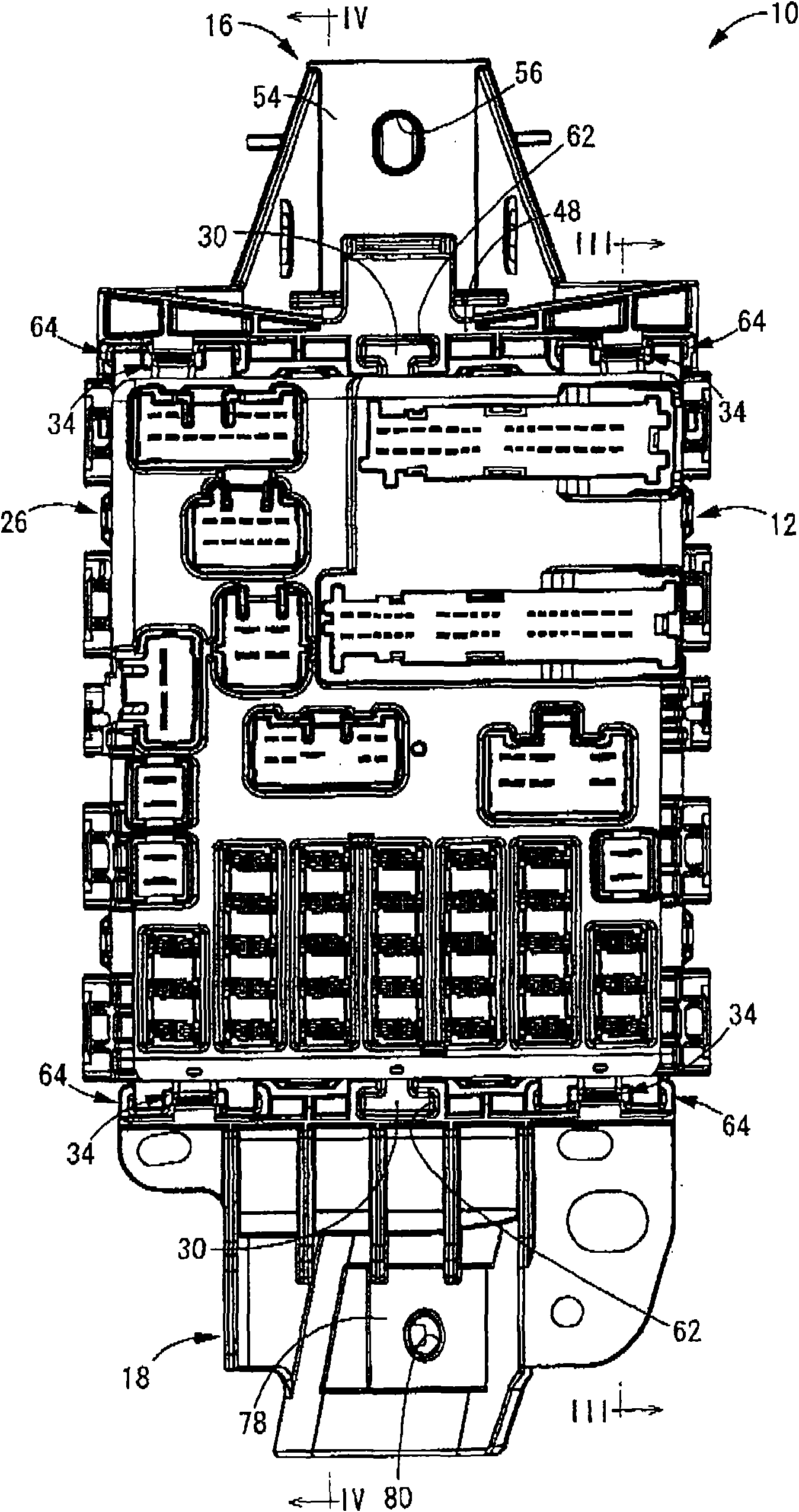
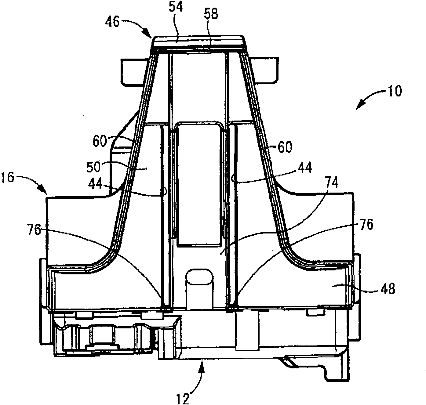
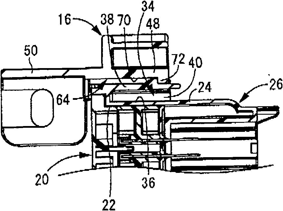
[0044] Figures 1 to 4 An electrical junction box 10 in one embodiment of the present invention is shown. This electrical junction box 10 is a vertical installation type electrical junction box in which an electrical junction box body 12 is attached to a vehicle body panel 14 by two brackets 16 and 18 serving as attachment legs (see Figure 4 ), and the electrical junction box body 12 is opposed to the vertical wall portion of the vehicle body panel 14. In principle, in the following, figure 1...


PUM


Abstract

The present invention provides a vertically mounted electrical junction box which can effectively prevent the dropping of the water flowing on a panel of vehicle body to an electrical junction box body (12) and comprises attached legs (16). The attached legs (16) are separated from the electrical junction box body (12) and are provided with a fixation part (46) used for the panel (14) of vehicle body at one end. Furthermore the attached legs are provided with disengageable junction parts (34,64) at the other end between the lower surface of the other end and the upper surface of the electric junction box body (12). The attached legs (16) are provided with water discharging grooves (44) on the upper surface. The water discharging grooves (44) extend from one end to the other end and are opened at the side of the panel (14) of vehicle body.

Description

technical field [0001] The present invention relates to an electric junction box mounted on a motor vehicle or the like, and more particularly, to an electric junction box including an electric junction box body provided with a waterproof structure. Background technique [0002] Generally, an electric junction box is provided on an electrical circuit of a motor vehicle or the like. A terminal board, a control board, and the like are installed in the electrical junction box. The electrical junction box is installed at a suitable location in the motor vehicle, such as a passenger compartment or an engine compartment. [0003] Water entering electrical junction boxes can easily cause serious damage to electrical circuits. Therefore, the installation position of the electrical junction box is set in the motor vehicle so that water does not enter the electrical junction box. However, it is very difficult to completely prevent water from entering the electrical junction box. ...

Claims


Application Information

Patent Timeline
Patent Type & Authority Applications(China)
IPC IPC(8): H02G3/08H05K5/00
CPCB60R16/0238H01R9/2425H01R2201/26H01R13/5227H01R4/64H01R9/2491
Inventor 余村猛
Owner SUMITOMO WIRING SYST LTD
Learn More