
Saucer-like air vehicle

An aircraft and disc-type technology, applied in the field of flying devices, can solve the problems of limiting the speed of the aircraft, high mechanical noise, and large frictional resistance, and achieve the effect of low vibration and noise, low resistance, and stable operation

Inactive Publication Date: 2010-09-22
蔡窿
View PDF5 Cites 2 Cited by
  • Summary
  • Abstract
  • Description
  • Claims
  • Application Information

AI Technical Summary

Problems solved by technology

There are many types of existing saucer aircraft, each with its own characteristics. Generally, the rotation is driven by the linkage between the rotating rotor and the rotating shaft of the body, and because of its high frictional resistance and high mechanical noise, it limits the speed of the aircraft. Its energy consumption is relatively large, so it is necessary to improve the aircraft to be better used in space operations

Method used


Image

  • Saucer-like air vehicle
  • Saucer-like air vehicle
  • Saucer-like air vehicle

Examples


Embodiment Construction

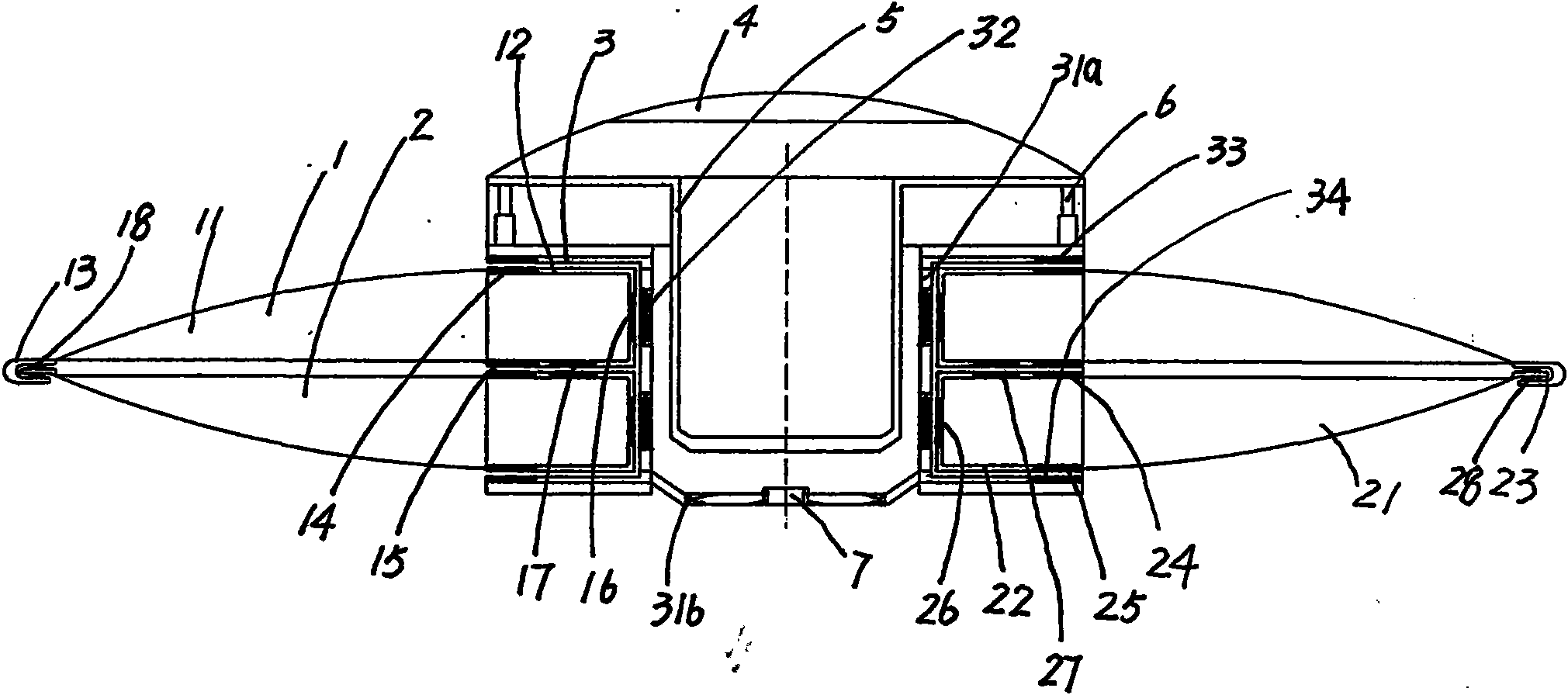
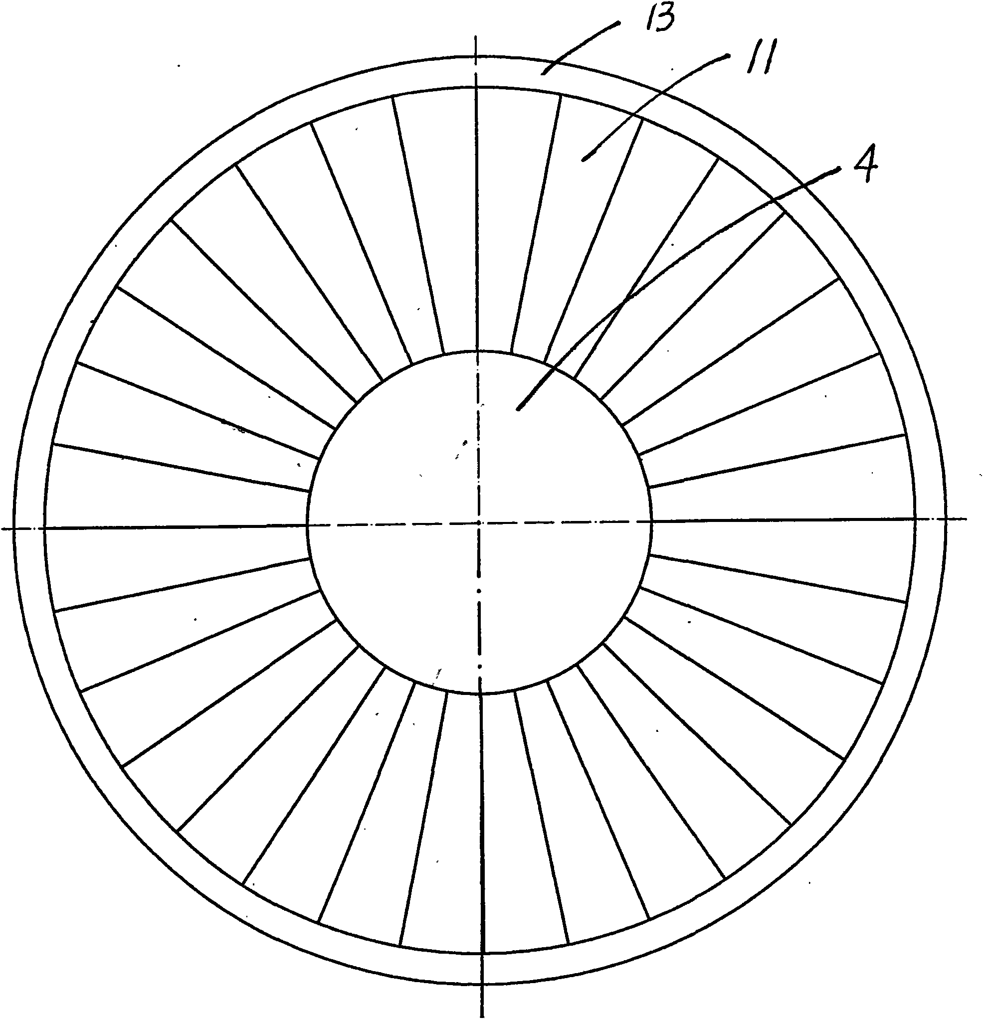
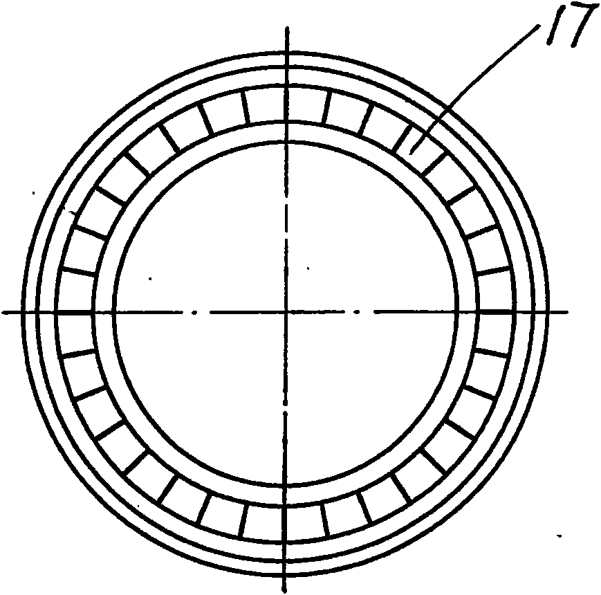
[0018] Reference attached figure 1 , Attached figure 2 , Attached image 3 , Attached Figure 4 , The saucer aircraft of the present invention includes a main power ring 1, a slave power ring 2, an air inlet cavity 3, a cavity cover 4, a load compartment 5, a direction adjustment mechanism 6, and a generator 7. The air inlet cavity 3 is respectively provided with opposite The rotating main power ring 1 and the slave power ring 2 are provided with a load compartment 5 in the inner cavity of the air inlet cavity 3, a cavity cover 4 is provided on the load compartment 5, and a cavity cover 4 is arranged between the load compartment 5 and the air inlet cavity 3. There is a direction adjustment mechanism 6, the direction adjustment mechanism 6 is at least four hydraulic mechanism devices, this embodiment is four hydraulic mechanism devices; the generator 7 is arranged at the air outlet end of the air inlet cavity 3, and the generator 7 is wind power Generator; The main power ring 1...


PUM


Abstract

The invention relates to a saucer-like air vehicle which comprises a primary power ring, a secondary power ring, an air inlet cavity, a cavity cover, a load chamber, a direction adjusting mechanism and a generator, wherein the primary power ring and the secondary power ring which rotate in opposite directions are respectively arranged on the air inlet cavity; the load chamber is arranged in the inner cavity of the air inlet cavity; the cavity cover is arranged on the load chamber; the direction adjusting mechanism is arranged between the load chamber and the air inlet cavity; the generator is arranged at the air outlet end of the air inlet cavity; the primary power ring and the secondary power ring are in end surface magnetic suspension structure; the primary power ring and the air inlet cavity are in end surface and side direction magnetic suspension structure; and the secondary power ring and the air inlet cavity are in end surface and side direction magnetic suspension structure. Because contact surfaces of mutual motion are in magnetic suspension structure, the overall operation is in a friction-free state; because rotating air flow enters the interlayer between the air inlet cavity and the load chamber, the taking off speed is improved, and the generating treatment is carried out simultaneously to provide energy for operating; and because the direction adjusting mechanism is arranged, the flight direction can be adjusted conveniently.

Description

Technical field [0001] The invention relates to a flying device, in particular to a saucer-type aircraft. Background technique [0002] After searching the relevant patent documents, there has not yet been found a saucer aircraft with the same structure as the present invention. There are many types of existing saucer-type aircraft, each with its own characteristics. Generally, the rotating wing and the shaft of the body are linked to drive rotation, and due to its high frictional resistance and high mechanical noise, it limits the lift-off speed of the aircraft, and at the same time Its energy consumption is relatively large, so it is necessary to improve the aircraft to better use it in space operations. Summary of the invention [0003] The purpose of the present invention is to provide a flying saucer that adopts a magnetic suspension structure, can make full use of the rotational force brought about by relative motion, has low rotational resistance, low noise, and can fully ...

Claims


Application Information

Patent Timeline
Patent Type & Authority Applications(China)
IPC IPC(8): B64C39/06
Inventor 蔡窿
Owner 蔡窿
Learn More