
Oil-pressure chain combined type push-and-pull vehicle mechanism

A technology for pushing and pulling a kiln car and pulling a kiln car, which is applied to the pushing and pulling device of a kiln car and in the field of pushing, can solve the problems of collapse of goods, single action of equipment, and increase of production cost.

Inactive Publication Date: 2010-08-25
万之江
View PDF0 Cites 6 Cited by
  • Summary
  • Abstract
  • Description
  • Claims
  • Application Information

AI Technical Summary

Problems solved by technology

[0002] 1. The existing push-pull cart mechanisms installed on the trolley mainly include the direct push type of the oil cylinder, the sprocket chain connection push plate type, and the sprocket chain oil cylinder push forward double-station combined type. The equipment has a single action, low production efficiency, and occupies an area of ​​​​and The volume is large, and the kiln car must be manually fed into the trolley, and the cart is not stable enough to work, which may easily cause the goods on the kiln car to collapse and increase the production cost.
[0003] 2. The movable pulley stroke amplification mechanism is usually used in vertical movement, and the mechanism works in one direction. The return stroke adopts passive reset, and the accuracy of the return stroke is difficult to guarantee.
For example, "Mechanical Design Handbook" "Second Volume", Chemical Industry Press 1991 reprint, the mechanisms shown in Figure 7-143 and Figure 7-144 on page P181 of the third chapter, respectively rely on springs or self-resetting, and cannot be in the horizontal direction. Simultaneously complete the task of high thrust and two-way work

Method used


Image

  • Oil-pressure chain combined type push-and-pull vehicle mechanism
  • Oil-pressure chain combined type push-and-pull vehicle mechanism
  • Oil-pressure chain combined type push-and-pull vehicle mechanism

Examples


Embodiment Construction

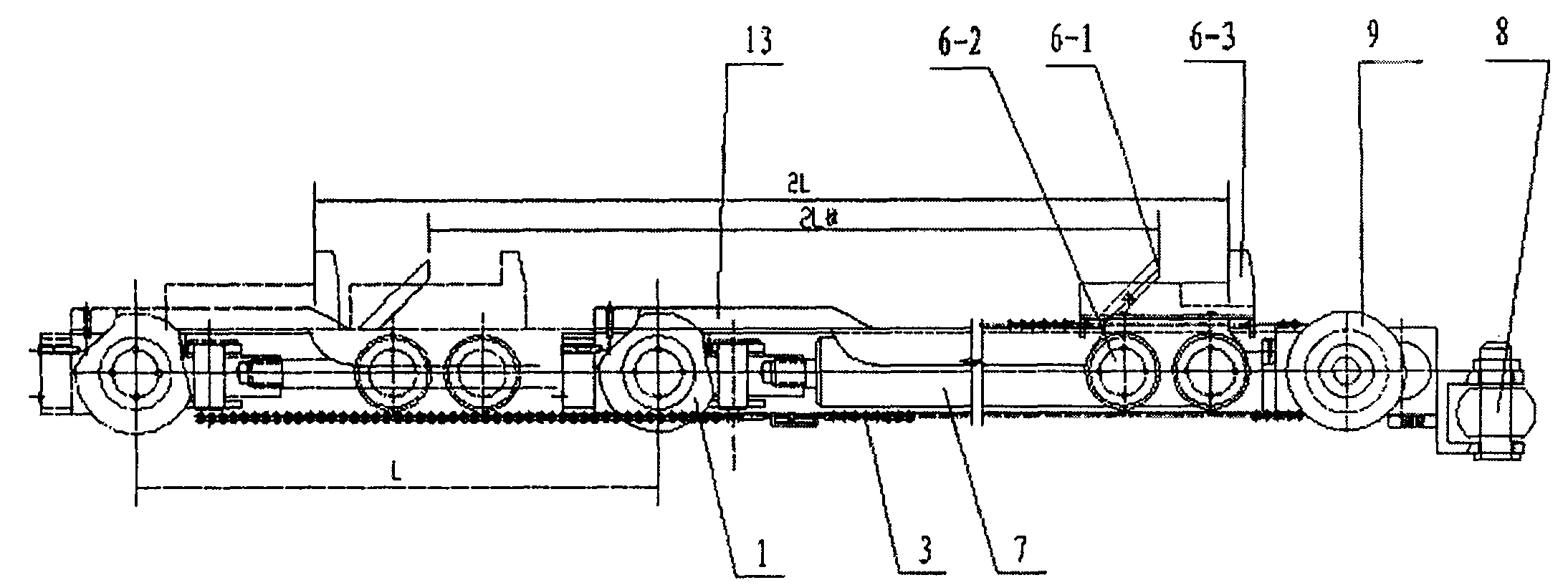
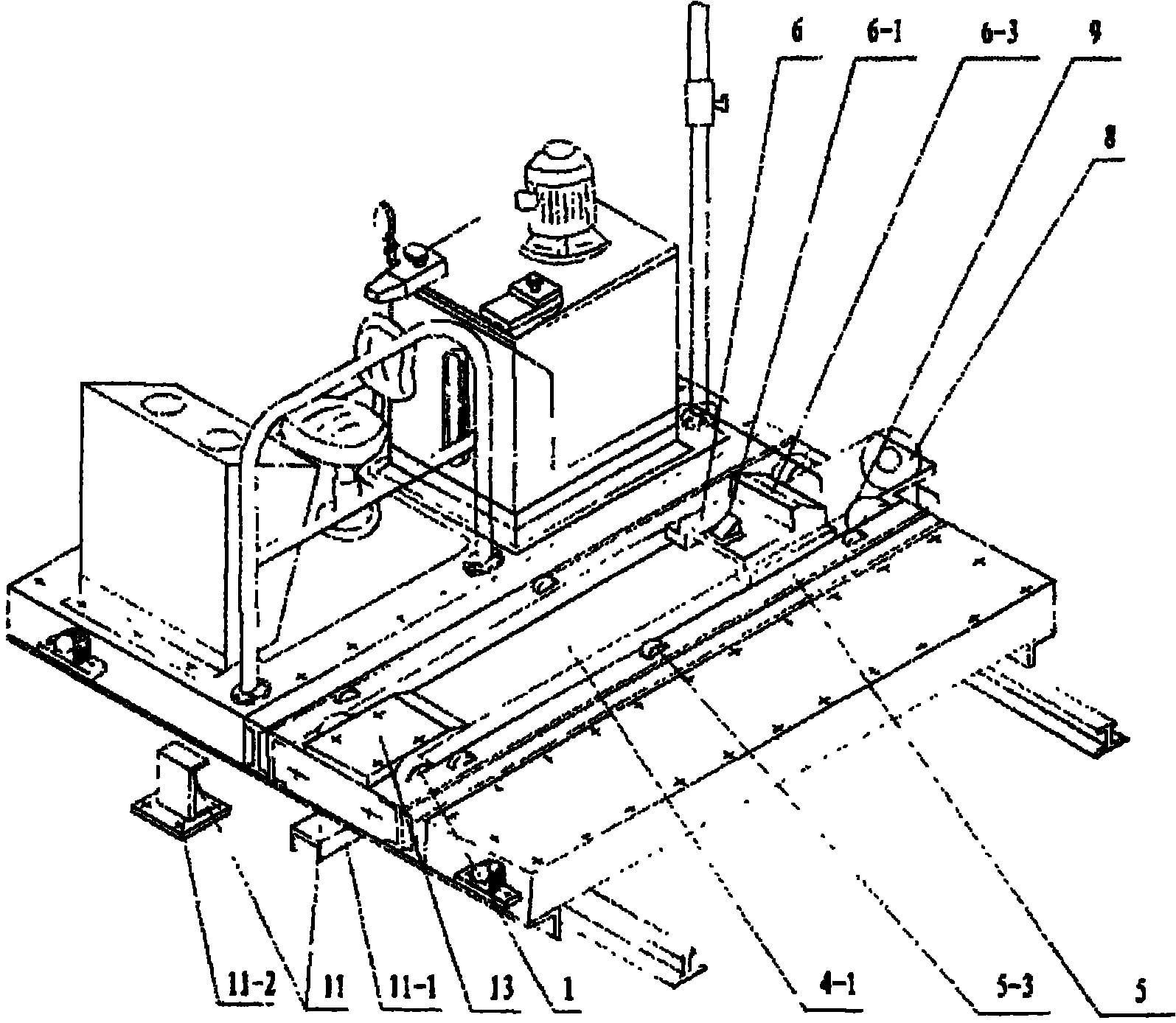
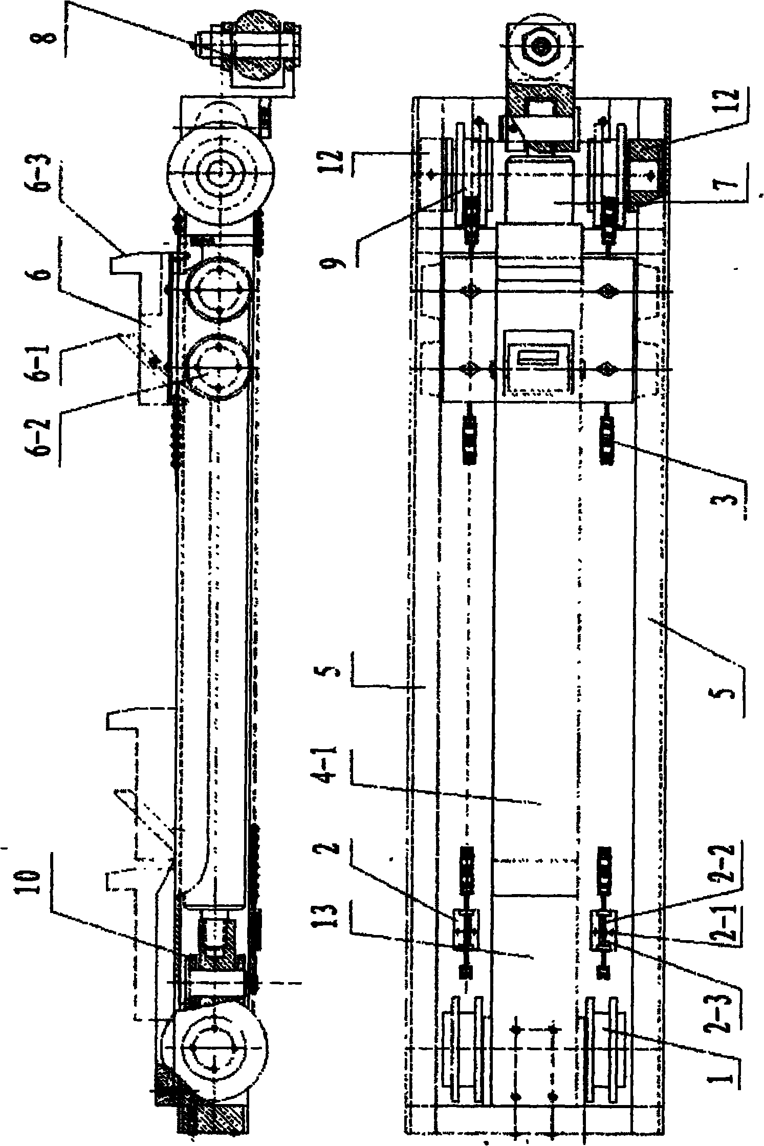
[0012] The main working principle of the present invention is: the trolley travels to the working point. When the work of pulling the cart starts, the oil cylinder 7 pushes the front pulley 1, thereby driving the chain 3 to move at twice the stroke of the cylinder piston, and the push-pull trolley 6 follows the chain 3 to move forward at the same speed. 6-1 After being pressed down by the push-pull plate on the kiln car, the lower part is equipped with a repeating position, and the travel switch that feeds back the travel of the pull car is activated. On, completed the work of pulling the cart. The trolley continues to drive to the unloading point and starts to push the cart. The push plate 6-3 on the push-pull trolley cooperates with the movable block 6-1 to push the push-pull plate of the kiln car, and the kiln car advances accordingly. The bottom of the movable block 6-1 on the top is lifted by the convex plate 13, and the fixed push plate 6-3 on the push-pull trolley push...


PUM


Abstract

The invention relates to a push-and-pull vehicle device, which is arranged on a trolley of a kiln vehicle in a conveying parallel rail and is used for pushing and pulling the kiln vehicle. In the device, two groups of front and rear moveable pulleys are arranged on a rigid member and are driven by an oil cylinder; a chain is connected with a support capable of adjusting the elasticity of the chain after winding the front and rear moveable pulleys and then is fixed on a trolley frame; the two ends of the push-and-pull vehicle used for pushing and pulling the kiln vehicle are hinged with the chain and horizontally moves forward and backward along with the chain; a convex plate used for controlling the push-and-pull vehicle to push and pull the vehicle is arranged on the rigid member which is connected with the front and rear moveable pulleys; and one end of an anti-dumping device and an anti-equilibrium device are arranged on the trolley frame. The device has the characteristics of large thrust, long travel of the push-and-pull vehicle and stable action during pushing and pulling the vehicle. After the device is arranged on the trolley, the kiln vehicle can be pulled on the trolley; the whole array of the kiln vehicle group can be pushed continuously after the kiln vehicle is pushed out of the trolley; and the area and self-gravity of the equipment are reduced by over a half. The device is also applied to equipment which has the requirements on large thrust, long travel and stable movement in the horizontal direction.

Description

1. Technical field [0001] The invention relates to a push-pull car mechanism installed on a trolley, in particular to a push-pull car device for pushing and pulling a kiln car installed on a trolley for transferring kiln cars in parallel tracks. 2. Background technology [0002] 1. The existing push-pull cart mechanisms installed on the trolley mainly include the direct push type of the oil cylinder, the sprocket chain connection push plate type, and the sprocket chain oil cylinder push forward double-station combined type. The equipment has a single action, low production efficiency, and occupies an area of ​​​​and The volume is large, and the kiln car has to be manually fed into the trolley, and the cart is not stable enough when it works, which may easily cause the goods on the kiln car to collapse and increase the production cost. [0003] 2. The stroke amplification mechanism of the movable pulley is usually used for vertical movement, and the mechanism works in one dir...

Claims


Application Information

Patent Timeline
Patent Type & Authority Applications(China)
IPC IPC(8): F27B9/14
Inventor 万之江
Owner 万之江
Learn More