Method and system for driving electromagnetic valve of diesel engine

A solenoid valve drive, diesel engine technology, applied in the direction of machines/engines, electrical control, mechanical equipment, etc., can solve the problems of inability to realize the "partially open" state, inability to realize fuel injection, etc., and achieve good inheritance and wide application prospects Effect

Inactive Publication Date: 2010-08-18
TSINGHUA UNIV
View PDF9 Cites 9 Cited by
  • Summary
  • Abstract
  • Description
  • Claims
  • Application Information

AI Technical Summary

Problems solved by technology

It can be seen that in this drive control method, the stable states of the moving parts are only "off" and "full open", and the "partially open" state cannot be realized, and the ideal "shoe-shaped" fuel injection cannot be realized.

Method used


Image

  • Method and system for driving electromagnetic valve of diesel engine
  • Method and system for driving electromagnetic valve of diesel engine
  • Method and system for driving electromagnetic valve of diesel engine

Examples


Embodiment Construction

[0022]The present invention will be described in detail below in conjunction with the accompanying drawings and embodiments.

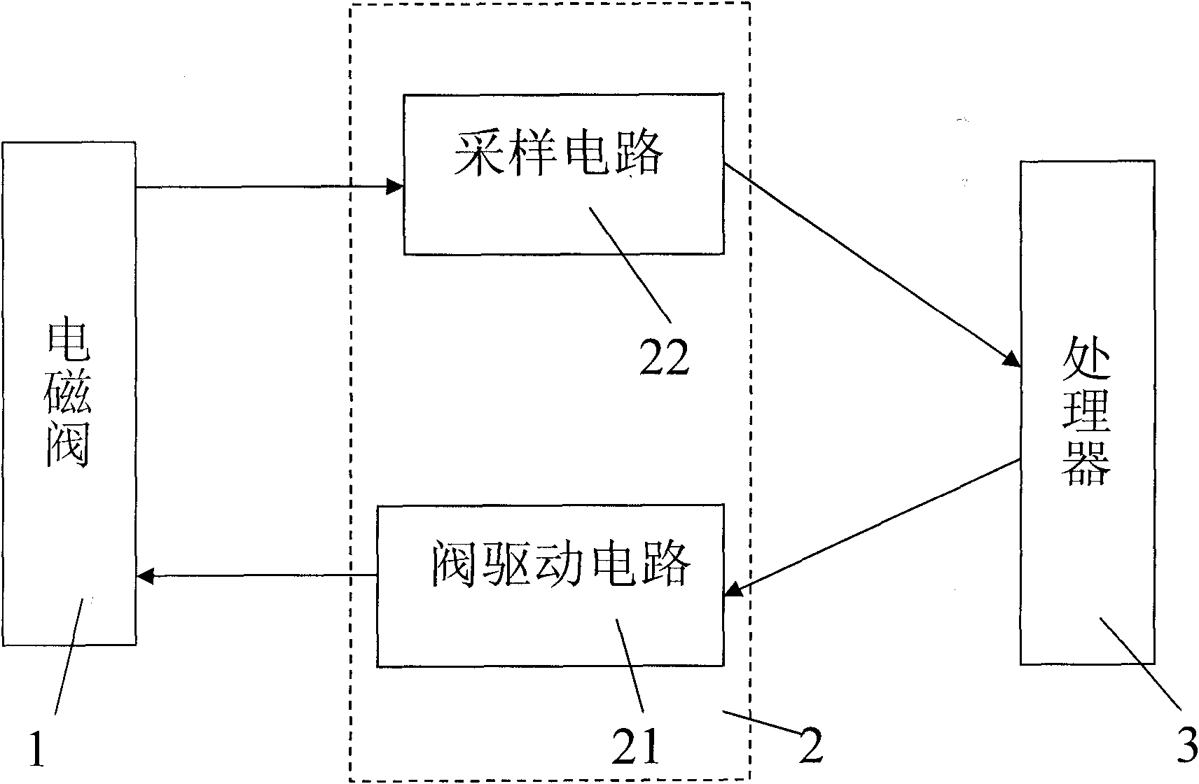
[0023] Such as figure 1 As shown, the driving system of the present invention includes a solenoid valve 1 , a sampling and driving unit 2 and a processor 3 . Solenoid valve 1 is the moving part in the fuel injection system, it is the injector solenoid valve in the common rail fuel injection system, and it is the high pressure pump solenoid valve in the unit pump fuel injection system. The sampling and driving unit 2 includes a sampling circuit 21 and a valve driving circuit 22 . The sampling circuit 21 samples the driving current of the solenoid valve 1 and sends the collected actual driving current to the processor 3 . The valve driving circuit 22 adjusts the driving current of the solenoid valve 1 according to the control signal of the processor 3 .

[0024] What the processor 3 of the present invention adopts is the FreeScale MC9S12XEP100 type sin...


PUM


Abstract

The invention relates to a method and a system for driving the electromagnetic valve of a diesel engine, comprising the following steps: (1) setting the driving system comprising the electromagnetic valve, a sampling and driving unit and a processor, wherein a diesel engine managing module is preset; (2) presetting the injection-control signal duration, the maximum values of a first, a second, a third and current-control stages durations, the driving current target values of the first, second, third and a fourth current-control stages in the engine managing module; (3) calculating the durations of the four current-control stages by the engine managing module according to the preset injection-control signal duration; and (4) comparing the differences between the driving current target values and the actual values in the first, second, third and fourth stages by the engine managing module, and adjusting the driving current of the electromagnetic valve so as to enable the electromagneticvalve to be switched off and then partially switched on in the first current-control stage, to be partially switched on in the second current-control stage, to be partially switched on and then totally switched on in the third current-control stage and to be totally switched off in the fourth current-control stage. The invention is mainly applied in the electromagnetic valve driving system, in particular to an electronically controlled diesel engine.

Description

technical field [0001] The invention relates to a diesel engine control method and its control system, in particular to a diesel engine solenoid valve driving method and its driving system. Background technique [0002] The ideal combustion of a diesel engine is mainly manifested in: NO x Low and particulate emissions combined with high thermal efficiency. The fuel injection law corresponding to the ideal combustion process is "slow in the initial stage, rapid in the middle stage, and fast in the late stage". However, neither the existing common rail fuel injection system nor the unit pump fuel injection system can realize the approximate "shoe-shaped" fuel injection law. In the existing common rail fuel injection system, since the fuel in the common rail cavity is always under high pressure, the fuel injection pressure is relatively high at the beginning of injection, so "shoe-shaped" injection cannot be realized. In the existing unit pump fuel injection system, since th...

Claims


Application Information

Patent Timeline
Patent Type & Authority Applications(China)
IPC IPC(8): F02D41/30
CPCF02D41/20
Inventor 张科勋刘磊杨福源欧阳明高
Owner TSINGHUA UNIV
Why Eureka
Try Eureka