
Sending method and system for measuring reference signals

A technology for measuring reference signals and sending methods, applied in the field of communications, can solve problems such as the decrease in the number of users, and achieve the effects of increasing the number of users, solving the decrease in the number of users, and increasing the number of users

Inactive Publication Date: 2014-11-05
ZTE CORP
View PDF6 Cites 0 Cited by
  • Summary
  • Abstract
  • Description
  • Claims
  • Application Information

AI Technical Summary

Problems solved by technology

[0014] And because it is proposed in the requirements of LTE-A that the number of users that the LTE-A system can accommodate should not be less than that of the LTE system, this requirement conflicts with the fact that the number of users decreases when multiple antennas transmit SRS.

Method used


Image

  • Sending method and system for measuring reference signals
  • Sending method and system for measuring reference signals
  • Sending method and system for measuring reference signals

Examples


example 1

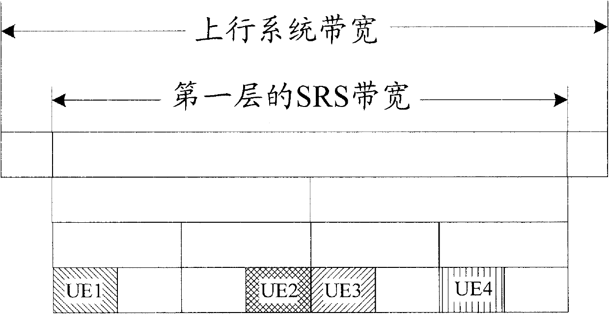
[0066] The base station sends control information to the UE for instructing the UE to send the SRS. The control information may be downlink control information and / or high-layer signaling, including: time-domain location indication information for sending SRS, transmission bandwidth, cyclic shift index value, RPF value, and frequency comb position used by the UE.

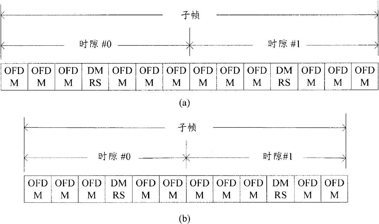
[0067] Wherein, the time domain position indication information for sending the SRS may be 1 bit, 2 bits or 3 bits, which is used to indicate the time domain position where the UE sends the SRS, and the time domain position is the time domain position where the two uplink DMRS symbols are located; cyclic shift The bit index value is 3 bits or 4 bits, which is used to indicate the cyclic shift used by the UE when sending the SRS, and the value can be 8, 12, or 16; the value of the RPF is 1 bit or 2 bits, and the value can be 2 or 16. 3 or 4; the frequency comb position used by the UE adopts 1 bit or 2 bits, and the c...

example 2

[0070] The base station sends control information to the UE to instruct the UE to send the SRS, where the control information can be downlink control information and or high-level signaling, including: time domain location indication information for sending the SRS, sending bandwidth, cyclic shift index value, The value of the RPF, the position of the frequency comb used by the UE.

[0071] The time domain position indication information for sending the SRS may be 1 bit, 2 bits or 3 bits, which is used to indicate the time domain position where the UE sends the SRS, and the time domain position is the time domain position where the two uplink DMRS symbols are located and the last one The time domain position where the data symbol is located; the cyclic shift index value is 3 bits or 4 bits, which is used to indicate the cyclic shift used by the UE when sending SRS, and the value can be 8, 12 or 16; the value of RPF is 1 bit Or 2 bits, the value can be 2, 3 or 4; the frequency ...


PUM


Abstract

Provided in the present invention are a method and a system for transmitting Sounding Reference Signals. The method includes the following steps: a terminal receives indication information sent from a base station; and the terminal transmits a first Sounding Reference Signal (SRS) and a second SRS to the base station at the same time on two Orthogonal Frequency Division Multiplexing (OFDM) symbols in a sub-frame indicated in the indication information respectively. With the invention, the quantity of users that could be contained in an LTE-A system is increased.

Description

technical field [0001] The present invention relates to the field of communications, and in particular, to a method and system for sending a sounding reference signal (Sounding Reference Signal, SRS for short). Background technique [0002] The uplink physical channel of the Long Term Evolution (Long Term Evolution, referred to as LTE) system includes a physical random access channel (Physical Random Access Channel, referred to as PRACH), a physical uplink shared channel (Physical uplink shared channel, referred to as PUSCH), physical uplink Control channel (Physical uplink control channel, referred to as PUCCH). The PUSCH has two different cyclic prefix (Cyclic Prefix, referred to as CP) lengths, which are a normal cyclic prefix (NormalCyclic Prefix, referred to as Normal CP) and an extended cyclic prefix (Extended CyclicPrefix, referred to as Extended CP). Each transmission subframe (Subframe) of PUSCH consists of two time slots (Slots). For different cyclic prefix length...

Claims


Application Information

Patent Timeline
Patent Type & Authority Patents(China)
IPC IPC(8): H04B7/06H04L5/00
CPCH04L5/0094H04L5/0048
Inventor 王瑜新戴博郝鹏梁春丽喻斌朱鹏张禹强
Owner ZTE CORP
Learn More