Vehicle shock absorber test-bed by adopting sine transmission device
A transmission device and shock absorber technology, which is used in vehicle suspension/shock absorber testing, railway vehicle testing, vehicle steering/jumping performance, etc., can solve problems such as inability to eliminate mechanism motion errors, unreliable test results, etc. Product performance quality inspection and testing technology level, low manufacturing cost, and the effect of eliminating mechanism motion errors
- Summary
- Abstract
- Description
- Claims
- Application Information
AI Technical Summary
Problems solved by technology
Method used
Image
Examples
Embodiment 1
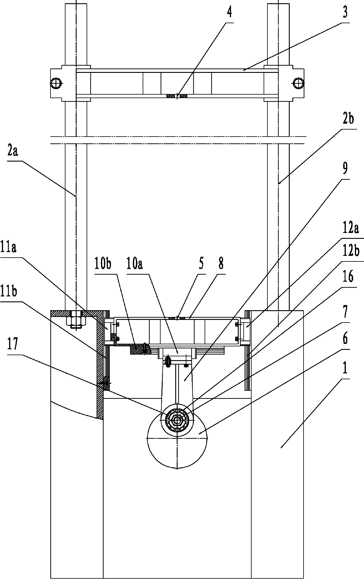
[0024] refer to figure 1 , a vehicle shock absorber test bench using a double guide rail type sinusoidal transmission device, including a machine base 1, on which guide posts 2a and 2b are installed, on which guide posts 2a and 2b are installed a beam 3, said The crossbeam 3 is provided with an upper fixture 4, and a crank disc 6, a crank shaft 7, a transmission device and an electric motor are installed in the said machine base 1, and the rotating shaft of the crank disc 6 is connected with the transmission device, and the said transmission device is connected with the motor, so that The crank shaft 7 is installed on the crank disc 6, and the axis of the crank shaft 7 is located at the eccentric position of the crank disc 6. The vehicle shock absorber test bench also includes a sinusoidal transmission, and the sinusoidal transmission includes a main Slider 8 and auxiliary slider 9, the lower end of described auxiliary slider 9 has bearing housing hole 16, and bearing 17 is ar...
Embodiment 2
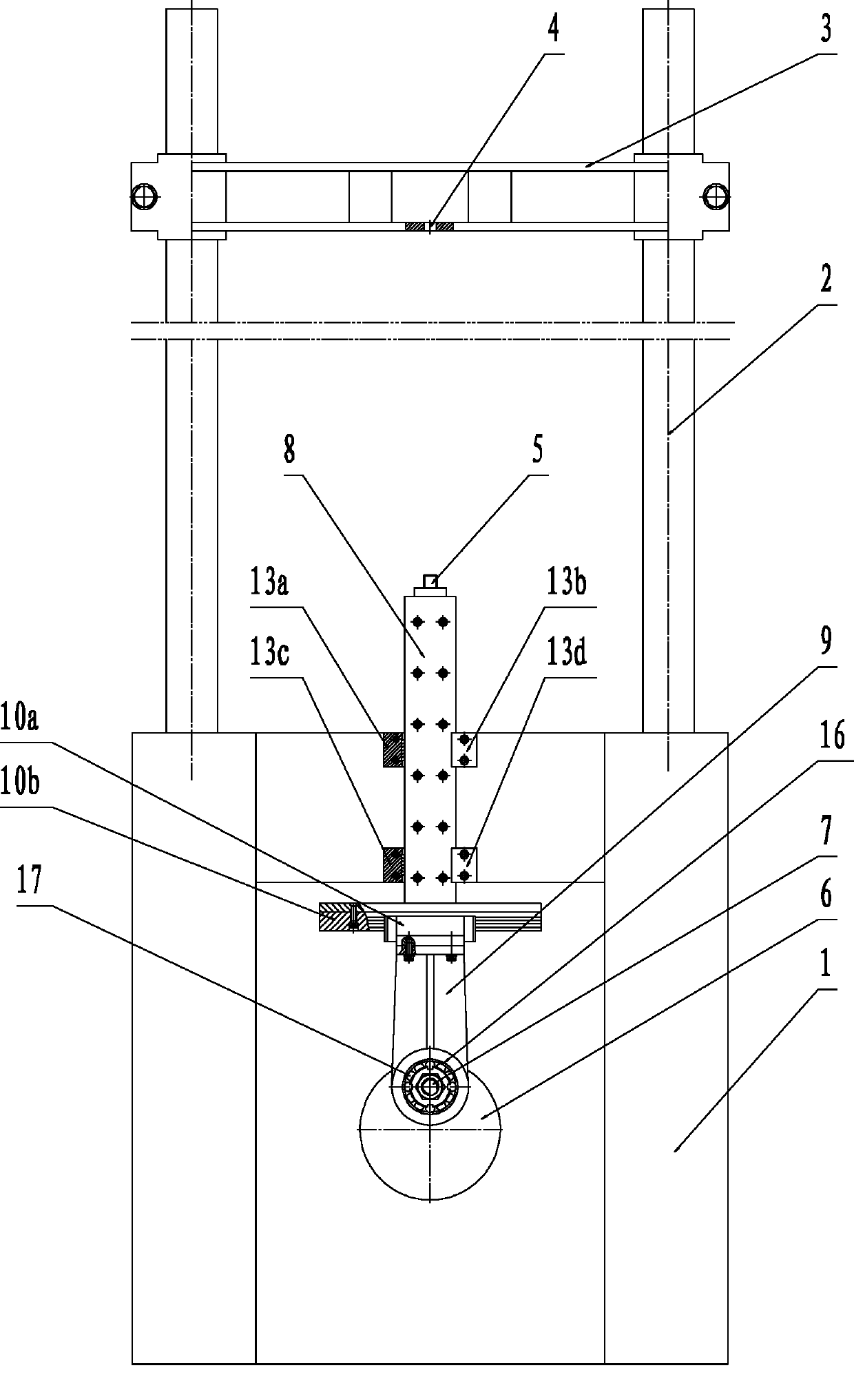
[0032] refer to figure 2 , a vehicle shock absorber test bench using a single guide rail type sinusoidal transmission device, comprising a base 1, a guide post 2 is installed on the base 1, a beam 3 is installed on the guide post 2, and a beam 3 is installed on the beam 3 There is an upper fixture 4, a crank disc 6, a crank shaft 7, a transmission device and an electric motor are installed in the base 1, the rotating shaft of the crank disc 6 is connected with the transmission device, the transmission device is connected with the motor, and the crank shaft 7 Installed on the crank disc 6, the axis of the crank shaft 7 is located at the eccentric position of the crank disc 6, and the vehicle shock absorber test bench also includes a sinusoidal transmission, and the sinusoidal transmission includes a main slider 8 and Auxiliary slide block 9, the lower end of described auxiliary slide block 9 has bearing seat hole 16, and bearing 17 is arranged between described bearing seat ho...
Embodiment 3
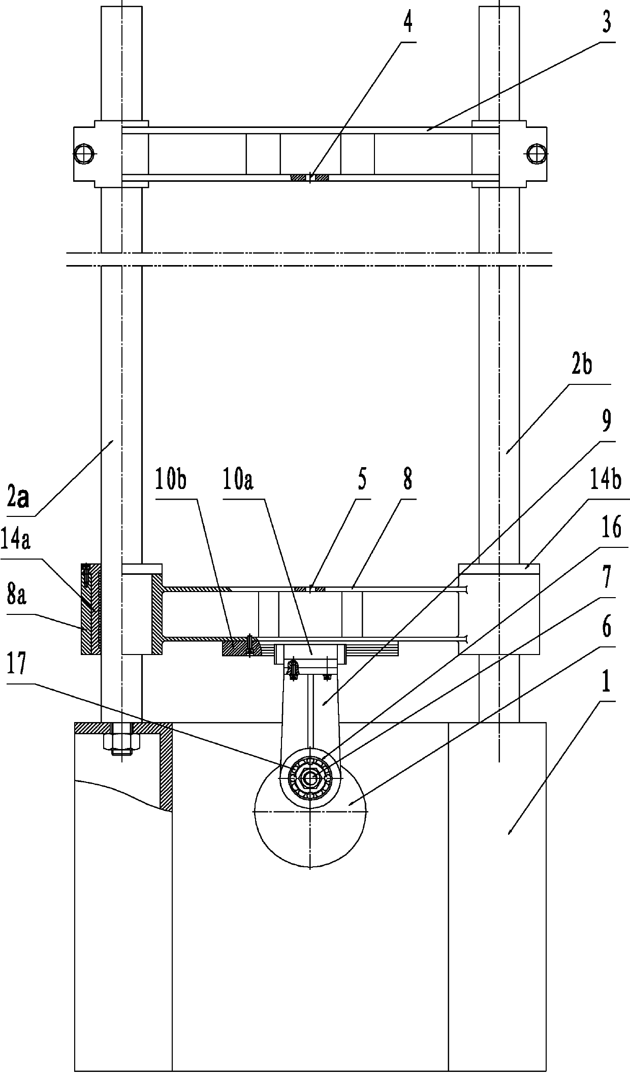
[0039] refer to image 3 , a vehicle shock absorber test bench using a double guide post type sinusoidal transmission, comprising a machine base 1, on which guide posts 2a and 2b are installed, and on which a crossbeam 3 is installed on the guide posts 2a and 2b, the The crossbeam 3 is provided with an upper clamp 4, and a crank disc 6, a crank shaft 7, a transmission device and a motor are installed in the support 1, and the rotating shaft of the crank disc 6 is connected with the transmission device, and the transmission device is connected with the motor. The crank shaft 7 is installed on the crank disc 6, the axis of the crank shaft 7 is located at the eccentric position of the crank disc 6, and the vehicle shock absorber test bench also includes a sinusoidal transmission, and the sinusoidal transmission includes The main slider 8 and the auxiliary slider 9, the lower end of the auxiliary slider 9 has a bearing hole 16, and a bearing 17 is arranged between the bearing hole...
PUM
 Abstract
Description
Claims
Application Information
 - R&D
- Intellectual Property
- Life Sciences
- Materials
- Tech Scout
- Unparalleled Data Quality
- Higher Quality Content
- 60% Fewer Hallucinations
Browse by: Latest US Patents, China's latest patents, Technical Efficacy Thesaurus, Application Domain, Technology Topic, Popular Technical Reports.
© 2025 PatSnap. All rights reserved.Legal|Privacy policy|Modern Slavery Act Transparency Statement|Sitemap|About US| Contact US: help@patsnap.com


