Projector fixing device

A technology for installing devices and projectors, used in projection devices, instruments, optics, etc.

Inactive Publication Date: 2012-06-20
UCHIDA YOKO LTD
View PDF3 Cites 0 Cited by
  • Summary
  • Abstract
  • Description
  • Claims
  • Application Information

AI Technical Summary

Problems solved by technology

A mounting device for the projector that can easily adjust the mounting state of the projector in such a situation has not been developed in the past.

Method used


Image

  • Projector fixing device
  • Projector fixing device
  • Projector fixing device

Examples


Embodiment 1

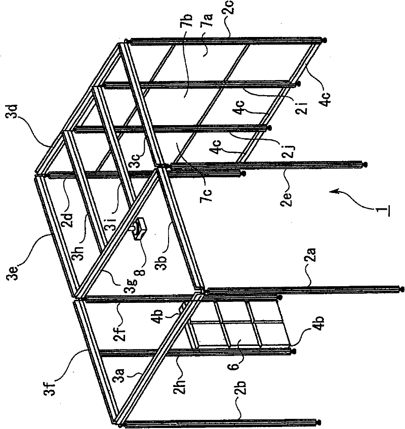
[0068] Here, details of a space structure using the projector installation device according to the present invention will be described with reference to the drawings. figure 1 It is a figure which shows the outline|summary of the whole space structure body 1. The spatial structure 1 is mainly composed of a plurality of columns, that is, rods 2a-2f, 2h-2j (hereinafter collectively referred to as "rods 2"), a plurality of beams, that is, beams 3a-3i (hereinafter collectively referred to as "beams 3"), and small beams. Beams 4b, 4c (hereinafter collectively referred to as "small beams 4") are composed of a combination. The rod 2 is a part extending vertically upward from the floor to support the space structure 1 , and the beam 3 and the small beam 4 extend horizontally along the floor to connect the rods 2 to each other or the beams 3 to each other.

[0069] in particular, figure 1 The shown spatial structure 1 is formed into a rectangular body, and has six rods 2a to 2f in th...

Embodiment 2

[0127]Next, another example of the mechanism for adjusting the rotation of the projector 8 will be shown. In the above-mentioned embodiment, the example in which the orientation of the image projected by the projector 8 is changed to an arbitrary orientation in the horizontal plane while the relative position of the projector 8 with respect to the beam 3 is fixed, however, in the present embodiment 2 shows an example in which the orientation of the image projected by the projector 8 is changed to an arbitrary orientation in the horizontal plane and in the vertical plane while the projector 8 is fixed. Thus, for example without Figure 28 Changing the relative position of the projector 8 relative to the beam 3 as shown can change the orientation of the projector 8 by about 90 degrees in the horizontal plane and by 45 degrees in the vertical plane, and it is possible to change the orientation of the projector 8 for two different screens or one screen. Adjust the projection posi...


PUM


Abstract

A projector fixing device for adjusting the fixing state of a projector (8) projecting a video image in a space structure for forming an arbitrary space by coupling one or a plurality of columnar bodies extending upward from the floor with one or a plurality of cross beam bodies (3) extending in the horizontal direction to the floor or by coupling the cross beam bodies (3) with each other. The projector fixing device comprises a fixing means for securing the projector to the cross beam bodies; a rotary coupling means (82) for coupling the securing means and the projector such that the projector is rotatable in a horizontal plane parallel with the cross beam bodies; and an operation portion (90) coupled to the projector which can project a video image in at least two directions by the rotary coupling means. Thus the screen position of the projector can be selected appropriately in the space structure where the projector is installed.

Description

technical field [0001] The present invention relates to an installation device capable of adjusting the installation state of information equipment or a projector installed in a space structure used for a display panel or the like in an office, an exhibition place, or the like. Background technique [0002] In an office, an exhibition place, etc., when constructing a shared space such as a meeting space or an exhibition space using information equipment, the design of the space structure is usually carried out according to various elements such as the size and weight of the information equipment used here. For example, since the size, weight, and number of displays and projectors used as information devices vary depending on the purpose of use of the space, it is necessary to design the space structure in a shape corresponding to them. However, due to the rapid development of recent information devices, new information devices appear one after another, or existing informatio...

Claims


Application Information

Patent Timeline
Patent Type & Authority Patents(China)
IPC IPC(8): G03B21/14
CPCG03B21/145G03B21/54H04N9/3129H04N9/3141
Inventor 国下超石桥晃杉本良佐藤宽之
Owner UCHIDA YOKO LTD
Why Eureka
Try Eureka